32
7. Control Elements and Connections
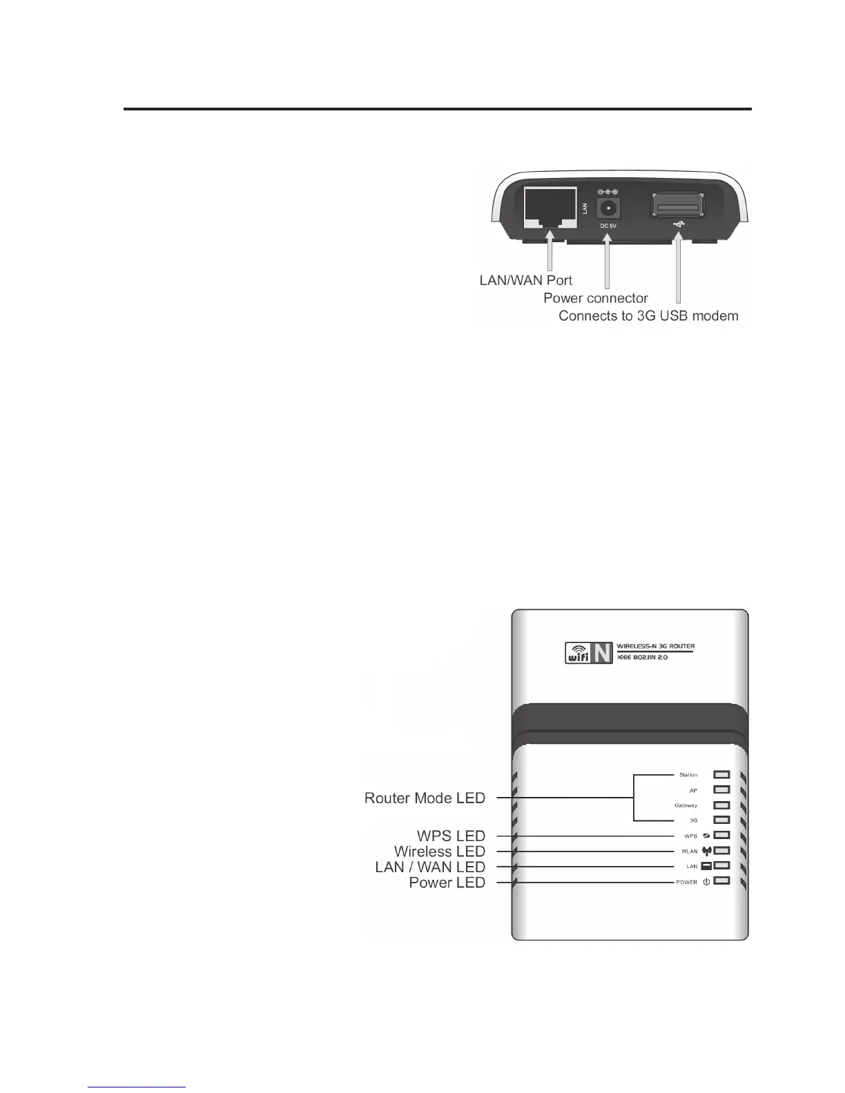
a) Router Connections
LAN/WAN Port Depending on the router’s
operating mode, a corre-
sponding device (DSL mo-
dem, computer, etc.) is con-
nected here with a 1:1-
linked network cable.
Power Connector For power supply. The in-
cluded mains adapter must
be connected here.
USB Port In the operating mode “3G Wireless”, the USB-UMTS modem is con-
nected here.
b) LEDs at the Router
Router Mode LED The respective LED shows which operating mode is active.
WPS LED This LED flashes quickly when the WPS is active.
Wireless LED The LED is lit during active WLAN reception or flashes during data
transfer.
LAN / WAN LED The LED is permanently lit if a
device is connected to the
router with a network cable; it
flashes during data transfer.
Power LED The LED is lit when the router is
connected to the power supply
via the mains adapter.