OPERATING & INSTALLATION INSTRUCTION 2-POST-LIFT
Secure the eye bearing with a hexagonal safety screw on the take-up bolt so that there remains a gap of 1 to
2 mm between the eye and the screw head.
Attention:
The self-securing screws only reach complete turning security after 24 hours.
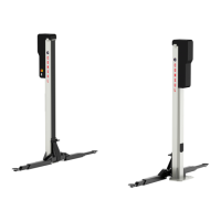
The H300 C lift with sill lifting chassis:
Attach the chassis and secure it against slipping out of the take-up bolts with M10 hexagonal safety screws.
The locking device on the lifting carriage can be removed if necessary.
The fixing brackets for the tension band must be sufficiently spaced from the column so that the tension
band does not catch and get damaged. The fixing brackets may need some follow-up adjustment.
The spindles must be oiled and the spindle oilers on the lifting carriage are to be filled with Consul Spindle
Oil using the observation holes on the columns (order no: 24960.3)
Should there be a buzzing noise from the tension bands when the lift is in drive then multi-purpose grease
can be applied to the back of the cover.
By doing a test run, check or reprogramme the end cut-out switches and the safety stop top and
bottom.When the lift’s operation has been checked according to BGG945 by a qualified engineer,
commissioning can begin.
The results of the check must be recorded in the check book.
Page 35