OPERATING & INSTALLATION INSTRUCTION 2-POST-LIFT
Safety lock device (load nut failure)
Your lift is equipped with a safety lock that tops the lift operating once a load bearing nut has failed. For
explanation of the function of the safety lock device, please read the following drawing.
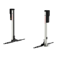
Fig. 2 and 3 show the position of the load bearing nut and respectively the safety nut with the angled safety
catch between the two nuts on the driving angles. The load carrying device are enclosed within the lifting
carriage and cannot be accessed from outside.
When running the lift in normal operation, there is a clearance between safety nut and carriage which allows
the safety nut to run unloaded.
If the thread of the load bearing nut is worn, the carriage falls on the safety nut and and activates the safety
lock which presses against the back wall of the column (see fig. 3).
In this defected state of the supporting elements, the lift can only be lowered. If the carriage is moved
upwards again, the safety lock catches on the bar on the back wall of the lift and stops the lift rising.
The locking mechanism must under no circumstances be disconnected.
If the lift stops about 10 mm above the ground level, the supporting elements are defect.
According to the safety lock device, the lift has to be out of function before repair by trained engineers.
Repairs carried out by no trained personnel may lead to serious accidents. !
To prevent on time the failure of the nut, proceed as follows:
Load bearing nut testing
with safety nut „trapezoidal thread Tr45x6”, available as special accessory (Ident-Nr.: 35416.7).
1. Remove the tightening strap, til safety nut in the carriage can be seen.
2. Move the lift upwards with the corresponding level and maintain.
3. Fixe the testing nut on the spindle, turn to the left til the testing nut draw up the supporting nut.
4. Lower the lift
5. Measure the slit between the supporting nut and the testing nut with a gauge or vernier.
If the wear is over 1mm, the supporting nut has to be replaced !
Page 42