8
SLIM Display Data
3B6
32.0 43.5
1.1 10.1
34.0 7 1 68
8
14 12 9
10
11 13
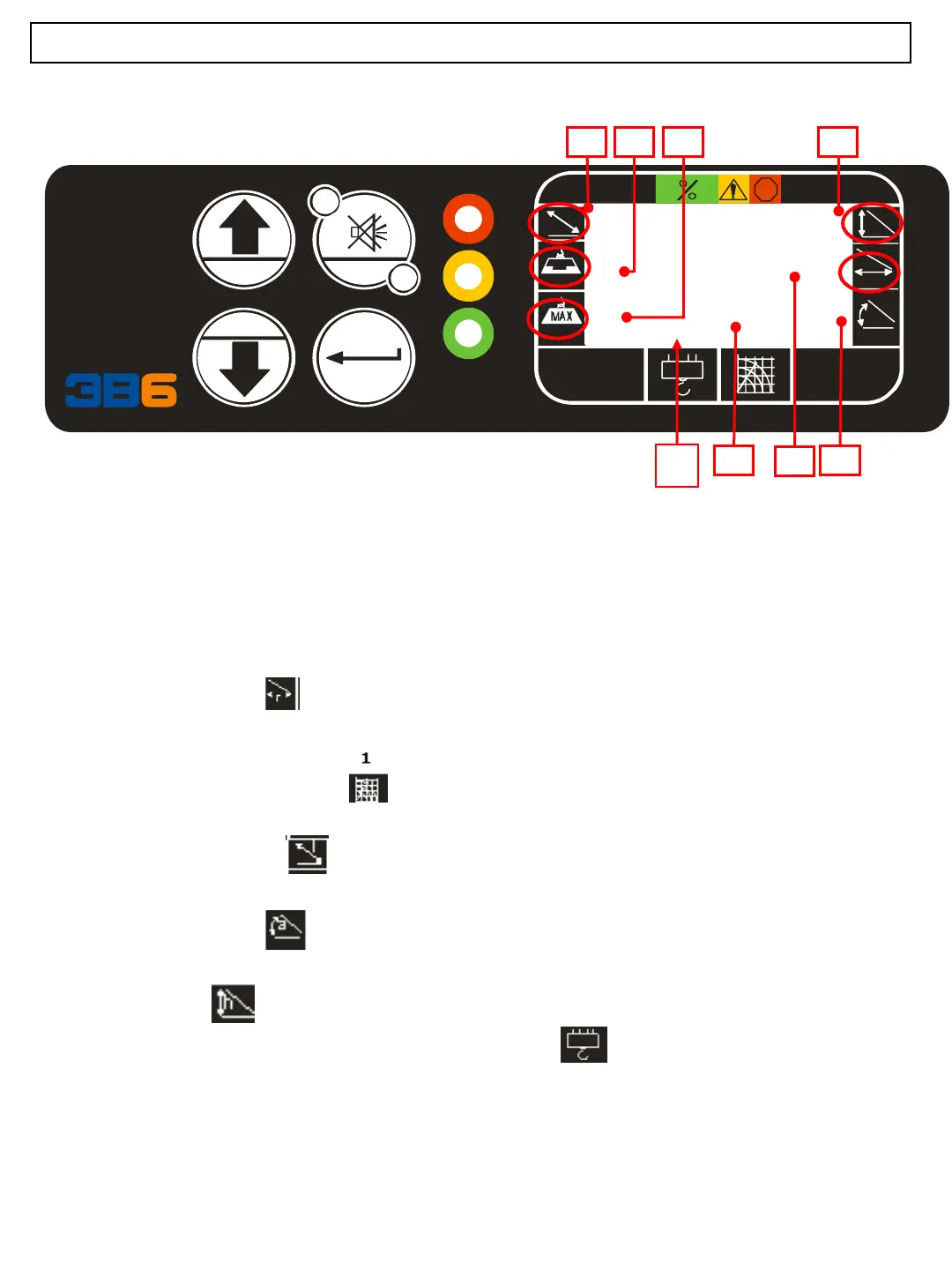
8) ACTUAL LOAD LIFTED: ACT Graphic Symbol : Indicates Actual load suspended,
value x 1000 in lbs or kgs
9) MAXIMUM CAPACITY LOAD: MAX Symbol; Indicates Maximum allowed load
value x 1000 in lbs or kgs
10) WORKING RADIUS: distance between the center of suspended load to center of turret
rotation point. Value feet and tenths or meters and tenths.
11) WORKING CONFIGURATION: Operating Mode or program selected.
value in feet and tenths or meter and tenths.
12) MAIN BOOM LENGTH: Distance from Boom rotation pin to boom sheave pin.
value in percentage 0-100%
13) MAIN BOOM ANGLE: boom angle in degrees relative to the ground
value in degrees.
14) BOOM HEIGHT: Distance from boom tip to ground
value in feet and tenths or meters and tenths.
15) PARTS of LINE : Number of wire rope rigging
15 15