UD53 User Guide
Issue code: 53nu3
B-1
B Aligning the Resolver Mechanically
Note
Use this procedure only when the procedure described in
Phase offset in Chapter 5 Setting Up the UD53 cannot be
performed.
Use the following procedure to precisely align the resolver with the motor
(for zero phase-offset). Precise alignment can be achieved only when the
resolver is connected to the Drive.
The Drive detects the exact points of polarity reversal of the (sine wave)
outputs. It would not be possible to identify these accurately on an
oscilloscope as in the case of standard encoders.
Warning
During this procedure, the motor shaft will be rotated
suddenly to a new position. Before starting, make sure it
will be safe for the motor shaft to be rotated.
1 Disconnect the motor from the Drive.
2 Ensure the shaft is unloaded and free to rotate.
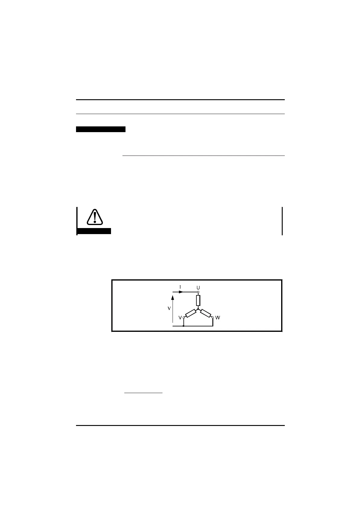
3 Apply a direct current of 50% of the motor rated current through the
motor windings, as shown in Figure B–1
Figure B–1 Connecting a motor to a DC source for mechanically aligning the
resolver shaft
The motor shaft will rotate to one of several positions depending on the
number of pole-pairs. For example, the shaft of a 6-pole motor will stop at
one of three places.
The resolver position is indicated by parameter 16.03 Resolver position.
The value will be given by:
n
No polepairs[. ]
××16384