UD53 User Guide
Issue code: 53nu3
18
6.3 Parameter descriptions
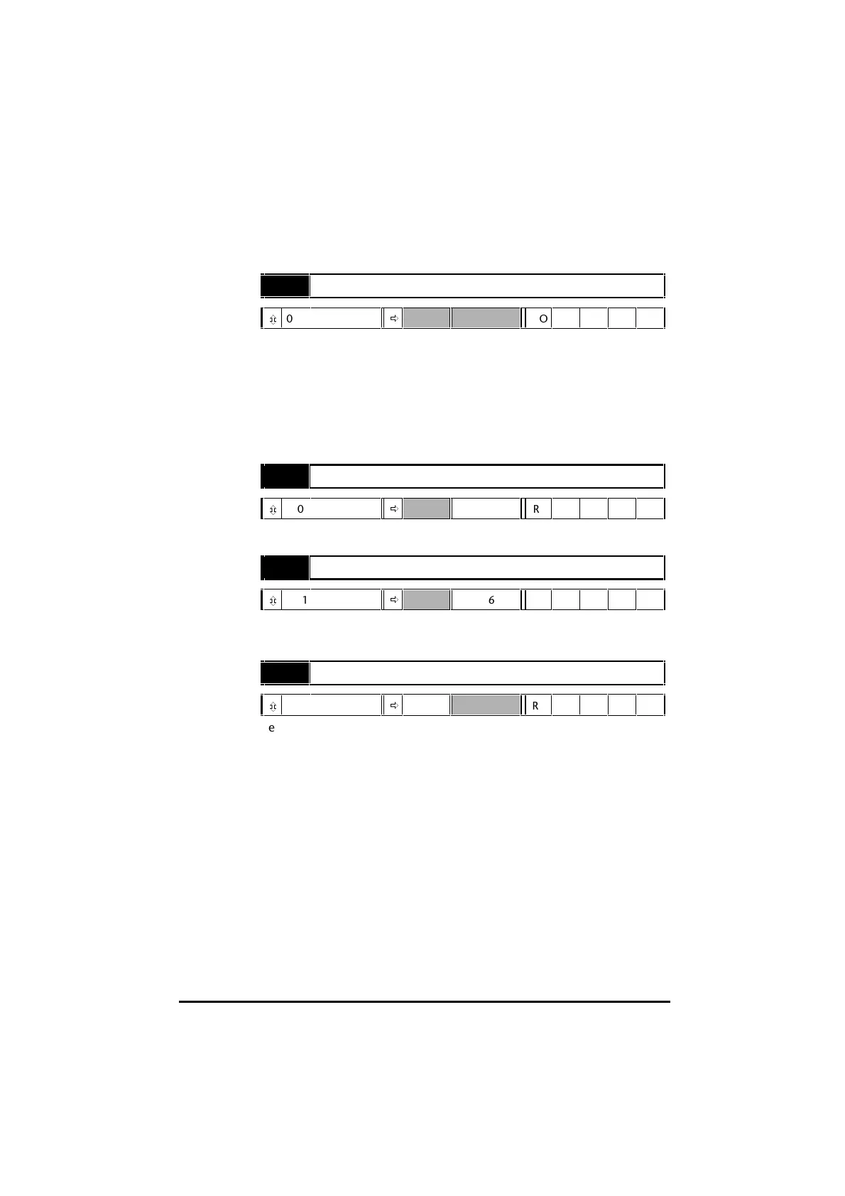
16.01 Option module fitted code
ô
0 ~ 100
ð
RO Uni P
16.01 indicates the type of small option module that is fitted in the Drive,
as follows:
0 No small option module
1 UD50 Additional I/O
2 UD51 Second encoder interface
3 UD53 Resolver interface
4UD52
SIN-COS encoder
16.02 Resolver RPM
ô
±30 000
ð
RPM RO Bi P
16.02 indicates the speed of rotation of the resolver.
16.03 Resolver position
ô
0 ~ 16383
ð
rev/16384 RO Uni P
16.03 indicates the absolute position of the motor shaft (the indication
takes into account any phase offset entered in 16.09 Resolver phase offset).
16.05 Resolver phasing test
ô
0 ~ 1
ð
0 RW Bit
Set 16.05 at 1 to initiate the resolver phasing test (on completion, 16.05
automatically returns to 0). See Phase offset in Chapter 5 Setting up the
UD53.