Safety
Information
Product
Information
Mechanical
Installation
Electrical
Installation
Getting
Started
Menu 0
Running
the motor
Optimisation Macros
Advanced
Parameters
Technical
Data
Diagnostics
UL Listing
Information
Unidrive User Guide 85
Issue Number: 9 www.controltechniques.com
7.2.2 Closed loop vector mode
Induction motor with speed feedback
Action Detail
Before power-up
Ensure:
• Enable signal is not given (terminal 30)
• Motor thermistor is connected or terminal 8 is linked to 0V
• Run signal is not given
• Motor is connected
• Feedback device is connected
The motor must be uncoupled from any gearbox or load before an autotune is carried out.
Power-up the
drive
• Change drive operating mode to closed loop vector
Set Pr xx.00 to 1253 / 1254 (USA).
Change Pr 0.48 to ‘CL.UECt’
Press the reset button
• Ensure the drive displays ‘inh’ (‘SEP.EC’ trip if 8V SINCOS encoder feedback is being used)
If the drive trips, see Chapter 12 Diagnostics on page 198.
Set feedback
device
parameters
Encoder
• Encoder power supply
Pr 3.23 = 0, 5V
Pr 3.23 = 1, 15V. (If Pr 3.23 = 1 then termination resistors should be disabled - Pr 3.24 = 1)
• Encoder PPR (pulses per revolution)
Enter PPR in Pr 3.21
Resolver
• The default setting is for a transformation ratio of 0.33 (3:1), if the resolver has a transformation
ratio of 0.5 (2:1), set Pr 16.10 = 1
SINCOS
• Encoder power supply
Pr 16.15 = 0, 5V
Pr 16.15 = 1, 8V. (Save parameters and cycle power to clear ‘SEP.EC’ trip)
• Encoder PPR (pulses per revolution)
Enter PPR in Pr 16.12
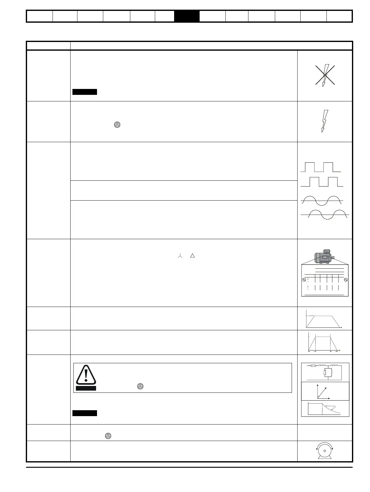
Enter motor
nameplate details
Enter:
• Motor rated power factor Pr 0.43
• Motor rated voltage in Pr 0.44 (V) - check if or connection
• Motor rated speed (synchronous speed - slip speed) in Pr 0.45 (rpm)
• Motor rated current in Pr 0.46 (A)
• Motor rated frequency in Pr 0.47 (Hz)
• Number of poles in Pr 0.42
Set maximum
speed
Enter:
• Maximum speed in Pr 0.02 (rpm)
Set acceleration /
deceleration rates
Enter:
• Acceleration rate in Pr 0.03 (s/1,000rpm)
• Deceleration rate in Pr 0.04 (s/1,000rpm) (If braking resistor fitted, set Pr 0.15 = FAST)
Autotune
• Close enable signal
•Set Pr 0.40 = 1 and wait for the drive display to return to ‘rdy’
If the drive trips, see Chapter 12 Diagnostics on page 198.
The motor must be uncoupled from any gearbox or load before an autotune is carried out.
Save parameters
Enter 1000 in Pr xx.00
Press the red reset button or toggle the reset digital input (ensure Pr xx.00 returns to 0)
Run Drive is now ready to run
NOTE
P
f 120×
N
s
------------------
=
Where: P = Number of poles, f = Rated frequency (Hz), N
s
= Synchronous speed (rpm)
Mot X XXXXXXXXX
No XXXXXXXXXX kg
IP55 I.cl F C 40 s S1
°
VHzmin
-1
kW cos
φ
A
230
400
50 1445 2.20 0.80 8.50
4.90
CN = 14.5Nm
240
415
50 1445 2.20 0.76 8.50
4.90
CN = 14.4Nm
CTP- VEN 1PHASE 1=0,46A P=110W R.F 32MN
I.E.C 34 1(87)
0.02
t
1000rpm
0.03
t
0.04
Once this parameter is set and the enable signal is given, the motor will accelerate up to
2
/
3
base frequency without a run command being given. Once the measurement is
complete, the motor will coast to a stop. The drive can be disabled at any time by
pressing the red button.
WARNING
NOTE
cos = ?
∅
L = ?
S
T
Nm
N rpm
= ?