Safety
Information
Product
Information
Mechanical
Installation
Electrical
Installation
Getting
Started
Menu 0
Running
the motor
Optimisation
Macros
Advanced
Parameters
Technical
Data
Diagnostics
UL Listing
Information
Unidrive User Guide 105
Issue Number: 9 www.controltechniques.com
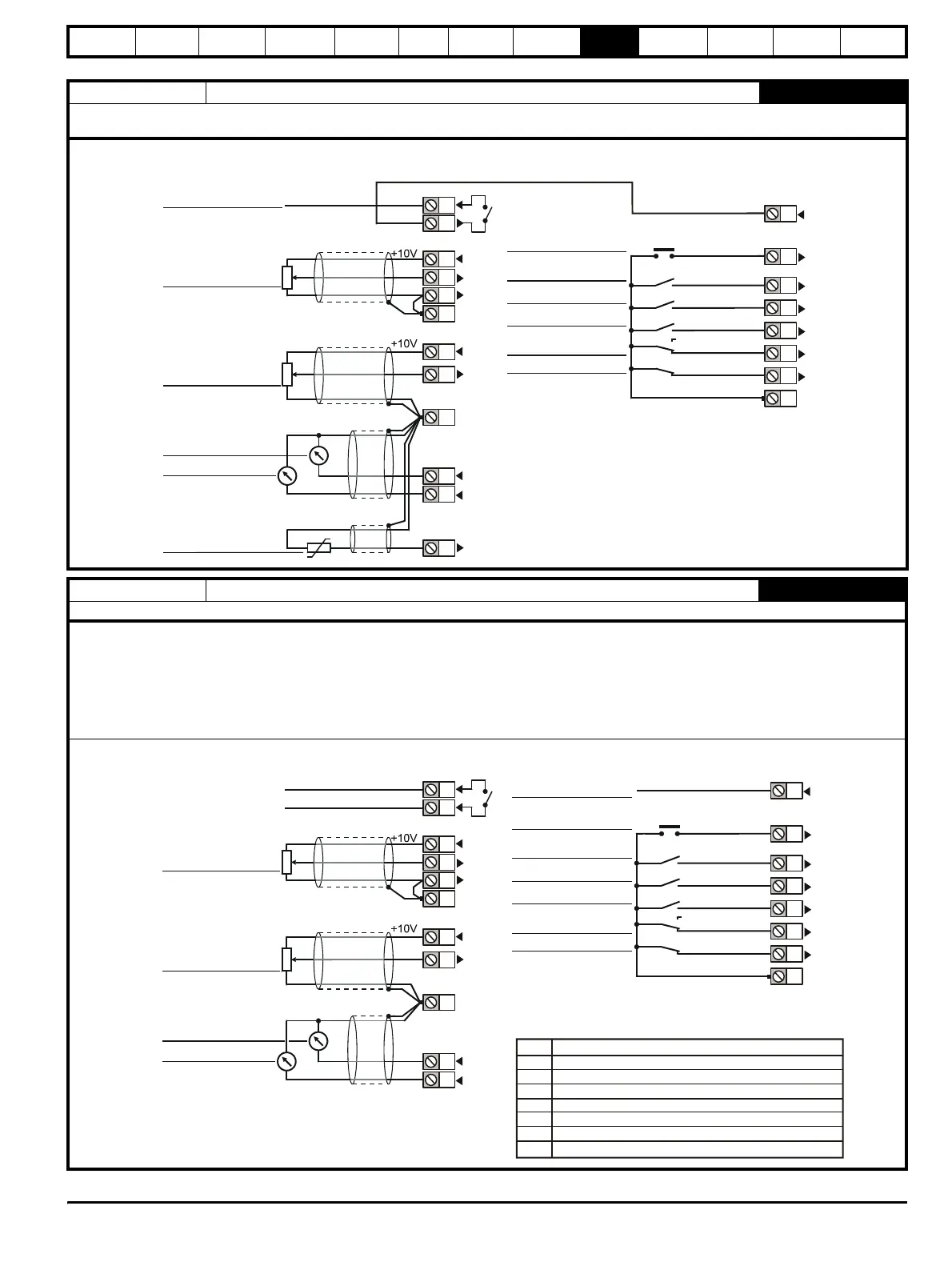
Macro 7 Brake control
2007
The brake control macro configures the drive to apply or release a mechanical brake on a motor in a crane or hoist application. The drive issues a
brake release signal via a digital output when the relevant conditions are met
Macro 8 Digital lock / shaft orientation
2008
This macro has two completely independent functions, digital lock and shaft orientation, selectable via Pr 0.15 {13.08}
Digital lock
The drive operates as a slave in a closed loop master-slave system. The slave motor is digitally locked to the master motor.
Shaft orientation
The motor speed is controlled in the same way as for default operation, but the motor shaft can be orientated to a specified angular position before
and/or after running the motor.
See Pr 13.08 in Chapter 10 Advanced Parameters for further information.
0V common
Analog
frequency/speed
reference 1
(remote) 0 ~ 10V
SPEED
TORQUE
0V common
BRAKE RELEASE
RESET
CL> JOG
RUN FORWARD
OL> External trip
CL> Drive enable
0V common
NALOG INPUT 1
NALOG INPUT 2
RUN REVERSE
ANALOG INPUT 1 /
INPUT 2
ignal
connector
Analog
frequency/speed
reference 2
(local) 0 ~ 10V
Motor thermistor
ignal
connector
24
25
26
27
28
29
30
31
1
2
4
5
6
3
7
11
9
10
8
4
0V common
Analog speed
reference 1
(remote) 0 ~ 10V
SPEED
TORQUE
0V common
ORIENTATION
COMPLETE*
RESET
JOG SELECT**
RUN FORWARD
Drive enable
0V common
NALOG INPUT 1
NALOG INPUT 2L
Status relay
Drive healthy
RUN REVERSE
ANALOG INPUT 1 /
INPUT 2
Signal
connector
Analog speed
reference 2
(local) 0 ~ 10V
Signal
connector
* Shaft orientation only
** Relative Jog when in Digital Lock mode
Pr
0 Speed control
1 Rigid digital lock with feed forward
2 Rigid digital lock without feed forward
3 Non rigid digital lock with feed forward
4 Non rigid digital lock without feed forward
5 Orientate when stopping the drive
6 Orientate when enabling and stopping the drive
0.15
1
2
4
5
6
3
7
11
9
10
4
24
25
26
27
28
29
30
31