Safety
Information
Product
Information
Mechanical
Installation
Electrical
Installation
Getting
Started
Menu 0
Running
the motor
Optimisation Macros
Advanced
Parameters
Technical
Data
Diagnostics
UL Listing
Information
142 Unidrive User Guide
www.controltechniques.com Issue Number: 9
* This parameter has a default setting of Fd (3) in the VTC variant.
** This parameter has a default setting of 9kHz (3) in the LFT variant.
Power rating
P
MAX
For definition of I
MAX
, see section Types of current range on page 138.
Where a parameter is represented by a text value, the value in brackets
in the range column is the setting used for serial communications.
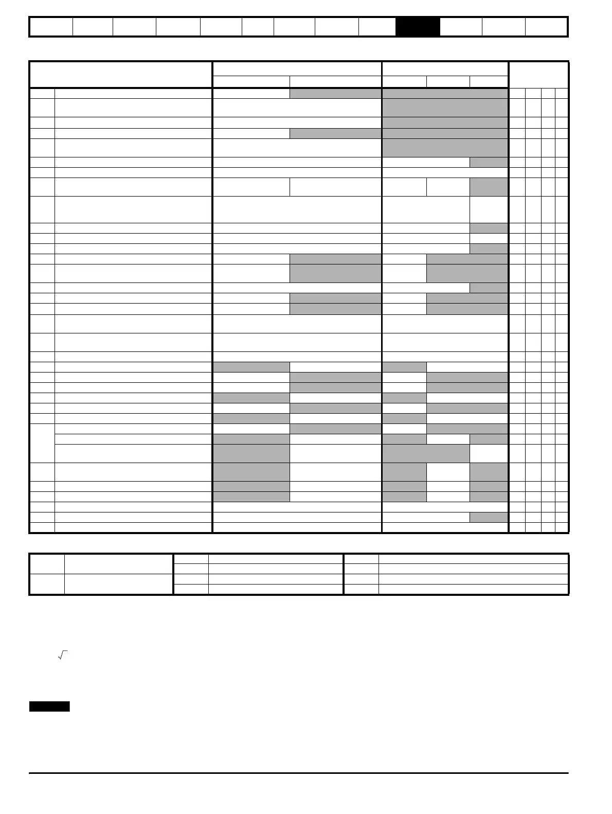
Parameter
Range(
Ú) Default(Ö)
Type
OL CL OL VT SV
5.01 Motor frequency ±[Pr 1.06]
RO Bi P
5.02 Motor voltage
200V drive: 0 to 264 V
400V drive: 0 to 528 V
RO Uni P
5.03 Tot a l m o t o r p o w e r
± P
MAX
kW
RO Bi P
5.04 Estimated motor speed {0.10} ± 6000 rpm
RO Bi P
5.05 DC bus voltage
200V drive: 0 to 415 V
400V drive: 0 to 830 V
RO Uni P
5.06 Motor - rated frequency {0.47} 0 to 1000.0 Hz EUR> 50, USA> 60
RW Uni
5.07 Motor - rated current {0.46} 0 to FLC A FLC RW Uni
5.08 Motor - rated speed {0.45} 0 to 6,000 rpm 0 to 30,000 rpm 0
EUR> 1,450
USA> 1,770
RW Uni
5.09 Motor - rated voltage {0.44}
200V drive: 0 to 240 V
400V drive: 0 to 480 V
200V drive: 220
400V drive: EUR> 400
USA> 460
0RWUni
5.10 Motor - rated power factor {0.43} 0 to 1.000 0.920
RW Uni S P
5.11 Motor - number of poles {0.42}2 to 32 46RWTxtP
5.12 Magnetizing current test
enable {0.40}0 or 1 0 RW Bit P
5.13 Dynamic V/f
select {0.09}0 or 1 0 RW Bit
5.14 Voltage mode
selector {0.07}
Ur_S (0), Ur_l (1),
Ur (2), Fd (3)
Ur_l (1)* RW Uni P
5.15 Boost voltage {0.08} 0 to 25.0 % 3
RW Uni
5.16 Jog boost-voltage 0 to 25.0 %
3 RW Uni
5.17 Stator resistance
0 to 32.000
Ω
0 RW Uni S P
5.18 PWM switching frequency
selector {0.41}
3 kHz (0), 4.5 kHz (1), 6 kHz (2), 9 kHz (3),
12 kHz (4)
3 (0)** RW Txt
5.19
High-stability space-vector modulation
enable
0 or 1 0 RW Bit
5.20 Quasi square-wave
enable 0 or 1 0 RW Bit
5.21 Field-gain reduction
enable 0 or 1 1RWBit
5.22 Maximum speed x10
select 0 or 1 0 RW Bit
5.23 Voltage offset 0 to 25.5 V
0 RO Uni S P
5.24 Motor leakage inductance
0 to 320.00 mH 0RWUniSP
5.25 Output frequency doubling
select 0 or 1 0 RW Bit
5.26 Cross-coupling compensation
enable 0 or 1 0RWBit
5.27
Slip compensation
enable 0 or 1 1 RW Bit
Auto-optimize rated speed
enable VT> 0 or 1 0 RW Bit
Phasing test for motors with high inertia
loads
SV> 0 or 1 0RWBit
5.28
Field-weakening gain compensation
disable
VT> 0 or 1 0 RW Bit
5.29 Motor saturation breakpoint 1
0 to 100 % 50 RW Uni P
5.30 Motor saturation breakpoint 2
0 to 100 % 75 RW Uni P
5.31 Voltage-controller gain 0 to 30 1 RW Uni P
5.32 Motor full load speed fine trim 0 to 0.99 rpm 0
RW Uni P
5.33 Thermal model-protection
enable 0 or 1 1 RW Bit
RO Read Only parameter
Uni Unipolar variable parameter R Reset required for new value to take effect
Bi Bipolar variable parameter S New parameter-value saved at power-down
RW Read / Write parameter
Txt Text variable parameter P Protected; forbidden as destination parameter
Bit Bit parameter FLC Full-load current (max. continuous), Pr 11.32 {0.33}
3I
MAX
×
Pr 5.09
1000
-------------------
×
NOTE