Safety
Information
Product
Information
Mechanical
Installation
Electrical
Installation
Getting
Started
Menu 0
Running
the motor
Optimisation Macros
Advanced
Parameters
Technical
Data
Diagnostics
UL Listing
Information
22 Unidrive User Guide
www.controltechniques.com Issue Number: 9
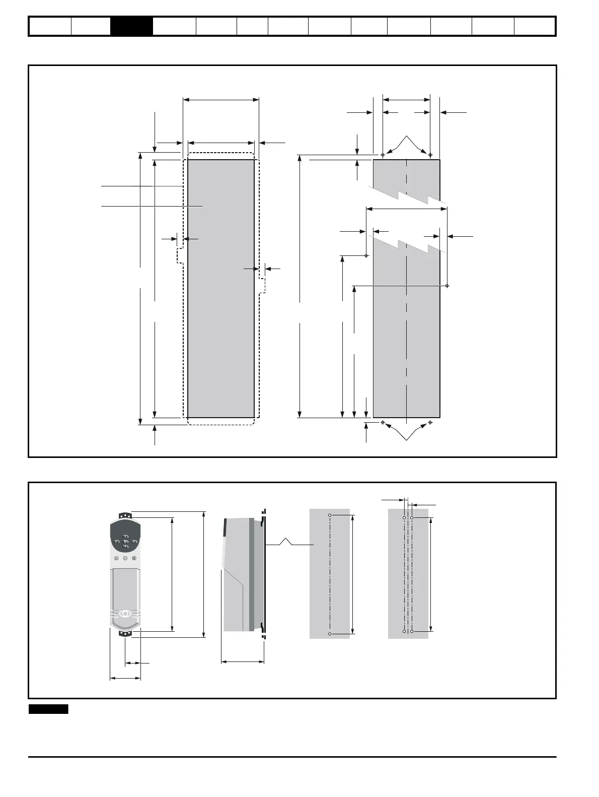
Figure 3-13 Unidrive Size 5 control module surface mounting
N
The Unidrive size 5 control module should be located within 2m of the
power module to allow the interconnections to be made using the ribbon
cables supplied with the power module.
203mm
7.992in
11mm
.4
in
∅
8mm
0.315in
315mm
282mm
Outline of
the power
module
Aperture
33.5mm
Location o
aperture in relation to
the outline of the power module
Locations and dimensions o
the
mounting holes in relation to the aperture
16.5mm
339mm
13.346in
590mm
23.228in
670mm
26.378in
1286mm
50.630in
10mm
0.413in
∅
11mm
0.433in
1252mm
49.291in
1319mm
51.929in
20mm
0.787in
∅
8mm
0.315in
12.402in
11.102in
0.650in
1.319in
20mm
0.787in
16.5mm
0.650in
37.5mm
1.476in
37.5mm
1.476in
28.5mm
1.122in
28.5m
1.122in
23.5mm
0.925in
33.5mm
1.319in
Figure 3-12 Unidrive size 5 backplate mounting holes and aperture
Back-plate
335mm
(13.189in)
368mm
(14.488in)
47.5mm
(1.870in)
95mm
(3.740in)
143mm
(5.630in)
345mm
(13.583in)
mm
(0.787in)
20mm
(0.787in)
332mm
(13.071in)
NOTE