Safety
Information
Product
Information
Mechanical
Installation
Electrical
Installation
Getting
Started
Menu 0
Running
the motor
Optimisation Macros
Advanced
Parameters
Technical
Data
Diagnostics
UL Listing
Information
Unidrive User Guide 53
Issue Number: 9 www.controltechniques.com
The default configuration of the above digital inputs and outputs are
different for Unidrive VTC. See Figure 4-16 Unidrive VTC default
terminal functions (European and USA) on page 51 and section
4.9.3 Unidrive VTC control terminal default configuration on page 54 for
details.
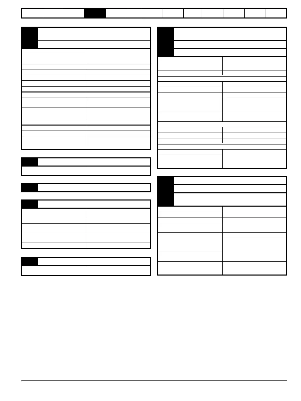
9 Analog output 1
OL> FREQUENCY output signal
CL> SPEED output signal
10 Analog output 2 TORQUE output signal
Type of output
Bipolar single-ended analog voltage or
unipolar current output
Mode controlled by...
7.19 & 7.22
Operating in Voltage mode
Output voltage range ±10V
Maximum output current 10mA peak
Load resistance
1k
Ω minimum
Protection Short-circuit proof
Operating in current mode
Current ranges
0 to 20mA
4 to 20mA
Maximum output voltage ±12V
Maximum load resistance
600
Ω
Equivalent input resistance
≤200
Ω at 20mA
Common to all modes
Resolution 10-bit plus sign
Update period
PWM switching frequency dependent
5.5ms for 3, 6, & 12kHz
7.4ms for 4.5 & 9kHz
11 0V common (analog)
Function
Common connection for external
analog devices.
21 0V common (digital)
22 +24V digital supply
Function
Supply for external digital signal
devices
Voltage tolerance ±10%
Nominal output current
200mA (total including any digital
outputs)
Overload output current
240mA (total including any digital
outputs)
Protection Current foldback above 240mA
23 0V common (digital)
Function
Common connection for external digital
devices.
24 Digital input / output F1
OL> AT-SPEED output
CL> AT ZERO SPEED output
25 Digital input / output F2 RESET input
26 Digital input / output F3 JOG SELECT input
Type of output
Negative or positive logic digital inputs,
or negative-logic push-pull or open
collector digital outputs
Input / output mode controlled by... Parameters
8.12, 8.15 & 8.18
Operating as an input
Logic mode controlled by... Parameter 8.27
Absolute maximum voltage range -3V to +30V
Input current when 0V applied ≥3.2mA
Negative-logic levels
Inactive state (input open-circuit):
>+15V
Active state: <+5V
Positive-logic levels
Inactive state (input open-circuit): >+5V
Active state: <+15V
Operating as an output
Open collector outputs selected by... Parameter 8.28
Maximum output current 200mA (total including terminal 22)
Overload output current 240mA (total including terminal 22)
Common to both modes
Voltage range 0V to +24V
Sample / Update period
PWM switching frequency dependent
5.5ms for 3, 6, & 12kHz
7.4ms for 4.5 & 9kHz
27 Digital input F4 RUN FORWARD input
28 Digital input F5 RUN REVERSE input
29 Digital input F6
ANALOG INPUT 1 / INPUT 2
SELECT INPUT
Type Negative or positive logic digital inputs
Logic mode controlled by... Parameter
8.27
Voltage range 0V to +24V
Absolute maximum
voltage range
–3V to +30V
Input current when 0V applied ≥3.2mA
Negative-logic levels
Inactive state (input open-circuit):
>+15V
Active state: <+5V
Positive-logic levels
Inactive state (input open-circuit): <+5V
Active state: >+15V
Sample period
PWM switching frequency dependent
5.5ms for 3, 6, & 12kHz
7.4ms for 4.5 & 9kHz