Unidrive
LV
model sizes 1 to 3 Installation Guide
Issue code: uliu1
2-4 Installing the Drive
Table 2–2 Cable sizes
Model Cable size
UNI 1201 1.5 mm
2
16 AWG
UNI 1202 2.5 mm
2
14 AWG
UNI 1203 2.5 mm
2
14 AWG
UNI 1204 2.5 mm
2
14 AWG
UNI 1205 2.5 mm
2
14 AWG
UNI 2201 2.5 mm
2
14 AWG
UNI 2202 4 mm
2
10 AWG
UNI 2203 4 mm
2
10 AWG
UNI 3201 6 mm
2
8 AWG
UNI 3202 10 mm
2
6 AWG
UNI 3203 16 mm
2
4 AWG
UNI 3204 25 mm
2
4 AWG
When EMC emission requirements are to be
met, shielded cable or steel wire armoured
cable may be required for the following:
•
AC supply to enclosure
• Drive to motor
• Drive to braking resistor when part of the
cable is outside the enclosure
For further details, see Wiring guidelines later in this
chapter.
Motor cable
STEP 3 Since capacitance in the motor cable
causes loading on the output of the Drive,
ensure the cable length does not exceed the
values given in Table 2–3.
Note
Maximum length of the encoder cable
When a Unidrive LV or Unidrive LFT LV is to
be used in a closed-loop system and with
long motor cables, the corresponding
length of the encoder cable may cause an
excessive supply-voltage drop between the
Drive and encoder. In this case, do not use
the Drive to supply the encoder; install a
separate
DC supply close to the encoder.
Table 2–3 Maximum cable lengths
Model Maximum cable length *
(
PWM switching
frequency at 3kHz)
m
UNI 1201 65
UNI 1202 100
UNI 1203 130
UNI 1204 200
UNI 1205 300
UNI 2201 ~
UNI 2203
300
UNI 3201 ~
UNI 3204
200
* Cable lengths in excess of the specified values may be
used only when special techniques are adopted; refer to
the supplier of the Drive.
The maximum cable length is reduced from that
shown in the table under the following
conditions:
•
PWM switching frequency exceeding
3kHz in model size 3 The maximum
cable length is reduced in proportion to the
increase in
PWM switching frequency, eg. at
9kHz, the maximum length is
1
/
3
of that
shown.
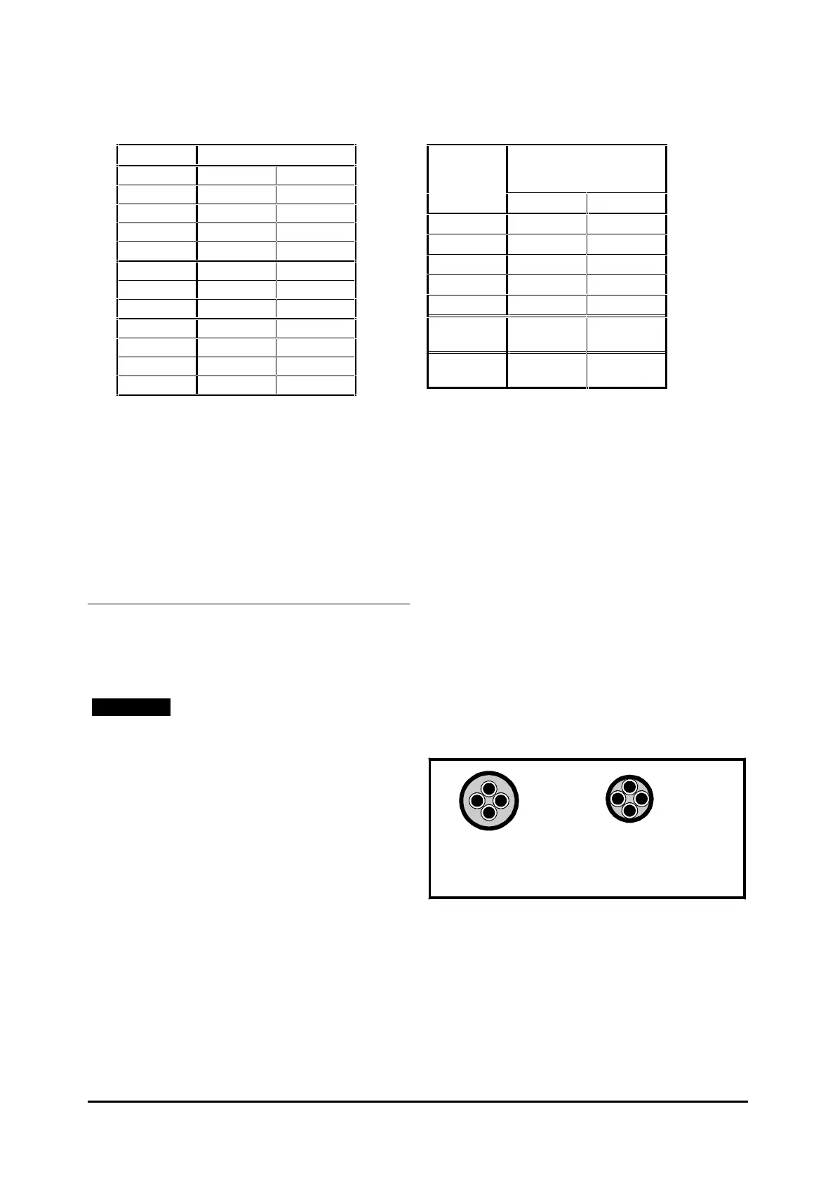
• High-capacitance cables Most cables
have an insulating jacket between the cores
and the armour or shield; these cables have a
low capacitance and are recommended.
Cables that do not have an insulating jacket
tend to have high capacitance; if a cable of
this type is used, the maximum cable length
is half that quoted in the table. (Figure 2–1
shows how to identify the two types.)
Normal capacitance
Shield or armour
separated from the cores
High capacitance
Shield or armour close
to the cores
Figure 2–1 Cable construction influencing
the capacitance
Multiple motors
Special requirements apply when the Drive is to
control more than one motor. Refer to
Appendix A Motor Connections.
 Loading...