Unidrive
LV
model sizes 1 to 3 Installation Guide
Issue code: uliu1
Installing the Drive 2-5
Isolator switch in the motor cable
An isolator switch may be connected in the
motor cable for safety purposes. Refer to the
following Warning and Note.
Warning
The isolator switch must not be
operated when the Drive is
enabled. (If an
AC-rated switch
is used and the Drive is
producing a low output
frequency when the switch is
opened, severe arcing can occur
which will prevent the switch
from breaking the circuit.)
A suitable interlock
arrangement can be used, such
as an isolator switch fitted
with additional contacts that
open before the main contacts.
These additional contacts
should be used to disable the
Drive.
Note
If the isolator switch is closed when the
Drive is enabled, the Drive may trip.
When EMC compliance is required, refer to Variations
in the EMC wiring recommendations later in this
chapter.
Output current,
PWM switching frequency,
Ambient temperature
Thermal protection
Note
The Drive can supply the rated current up
to an ambient temperature of 40
o
C (104°°F)
(depending on the
PWM switching frequency
used).
The Drive can be operated in an ambient
temperature up to 50
o
C (122
o
F) at de-rated
output current. In this case, ensure the
value of parameter 0.46 Motor rated current
does not exceed the value given in
Table 2-5.
The Drive has two forms of thermal protection for
the power output stage (IGBT bridge), as follows:
1. A thermistor mounted on the heatsink monitors
the heatsink temperature. If this exceeds 95°C
(203°F), the thermistor will cause the Drive to
trip. The display will indicate Oh2.
2. Intelligent thermal modelling estimates (by
calculation) the junction temperature of the
IGBTs. There are two temperature thresholds
which cause the following to occur:
• If the first threshold is reached, the
PWM
switching frequency is halved in order to
reduce dissipation in the IGBTs. (When the
frequency is halved, the value of parameter
0.41
PWM switching frequency remains at the
value set by the user; if the frequency is 3kHz
or 4.5kHz, no halving occurs). Then at one
second intervals, the Drive will attempt to
restore the original
PWM switching
frequency. This will be successful if the
estimated temperature has reduced
sufficiently.
• If the estimated temperature has continued
to rise and reaches a second threshold, the
Drive will trip. The display will indicate Oh1.
S
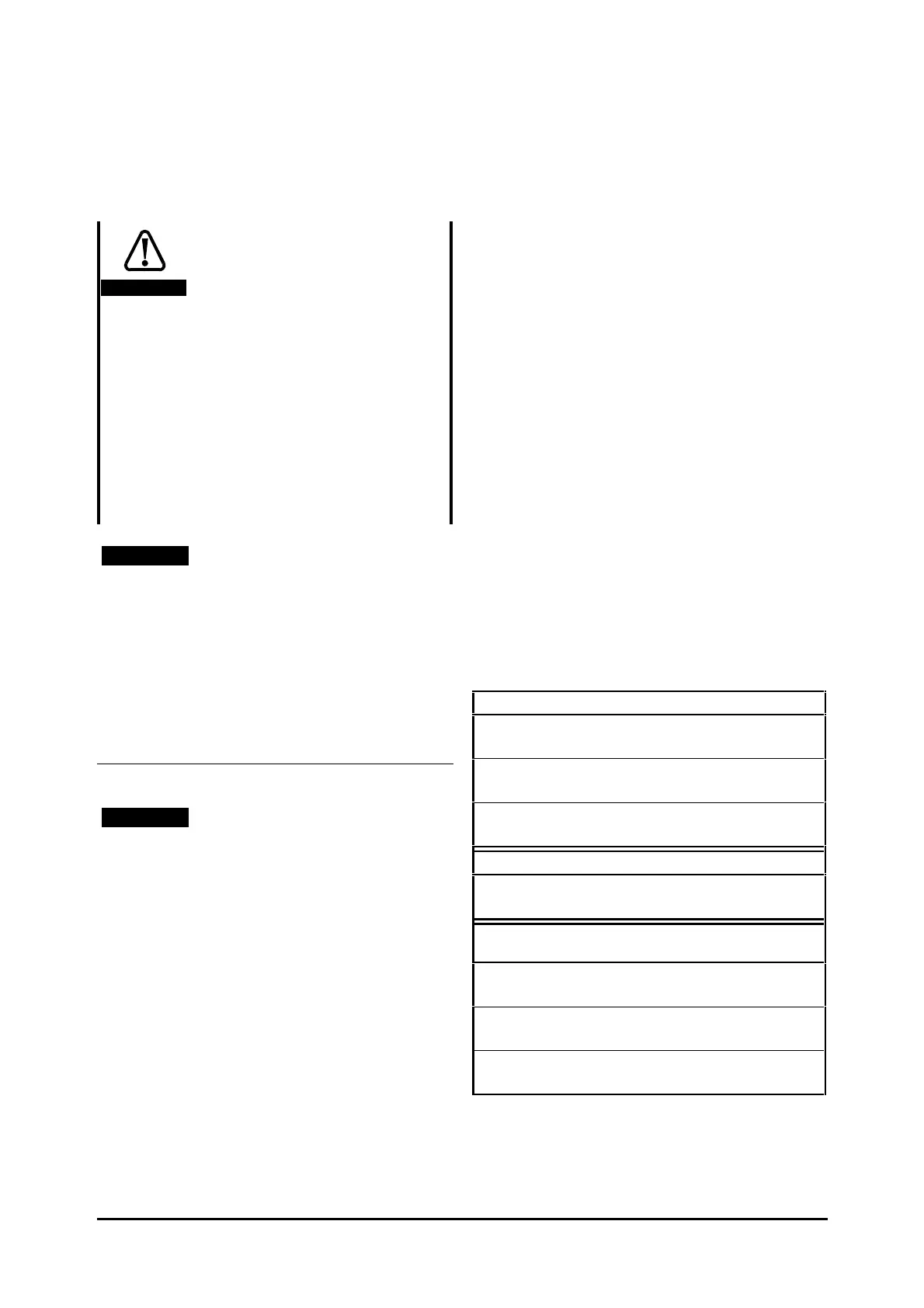
TEP 4 Note that the Drive can deliver an
overload current, as shown in Table 2–4.
Table 2–4 Overload current
Unidrive LV
Open-loop
Up to 150% of the rated current for 60 seconds
Closed-loop Vector
Up to 175% of the rated current for 60 seconds
Closed-loop Servo
Up to 175% of the rated current for 4 seconds
Unidrive VTC LV
For a variable-torque load
Up to 120% of the rated current for 60 seconds
Unidrive LFT LV operating on
standard S4/S5 duty cycle
Open-loop
Up to 150% of the rated current
Closed-loop Vector
Up to 175% of the rated current
Closed-loop Servo
Up to 175% of the rated current
 Loading...