16 Guide pas à pas pour l’Unidrive M100/M101/M200/M201/M300
Édition : 1
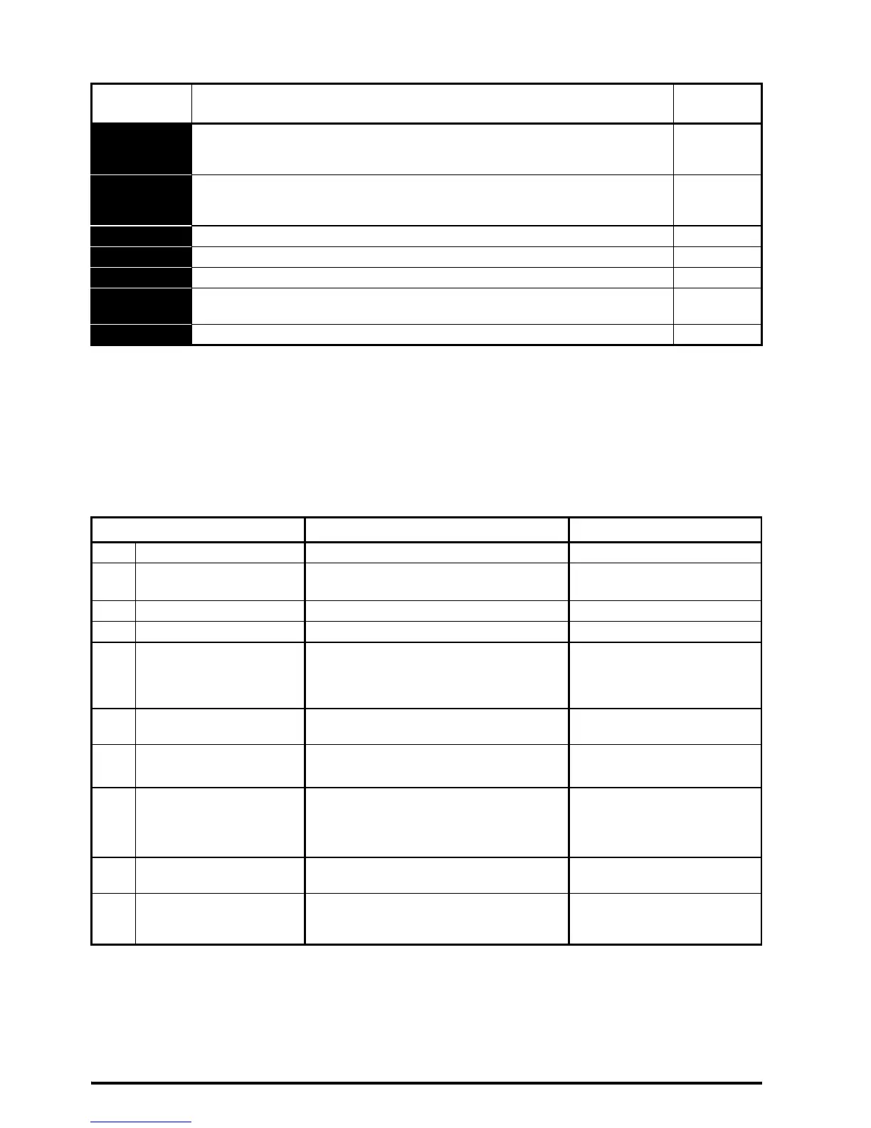
Tableau 10-1 Indications d'état
ÉTAPE 11 : Explication des paramètres principaux et restauration
des valeurs par défaut
Lors de la modification d'un paramètre, la nouvelle valeur est sauvegardée en appuyant sur la touche Entrée pour
passer du Mode Modification au Mode Visualisation.
Restauration de la valeur par défaut des paramètres :
1. S’assurer que le variateur est verrouillé, la borne 11 (ou les bornes 31 et 34 de l’Unidrive M300) est ouverte.
2. Sélectionner ‘Def.50’ (paramètres 50 Hz) ou ‘Def.60’ (paramètres 60 Hz) dans Pr 00.
3. Appuyer sur la touche Reset rouge.
Mnémonique Description
Sortie du
variateur
inh
Le variateur est verrouillé et ne peut pas être mis en marche. Le signal de
déverrouillage variateur n'est pas appliqué à la borne de déverrouillage ou est
réglé sur 0.
Désactivée
rdy
Le variateur est prêt pour la mise en marche. Le déverrouillage du variateur est
actif mais l'onduleur du variateur n'est pas actif parce que le signal de marche
final n'est pas actif.
Désactivée
StoP Le variateur est arrêté/maintient le moteur à vitesse nulle. Activée
S.Loss Une condition de perte d'alimentation a été détectée. Activée
dc inj Le variateur applique un freinage par injection de courant DC. Activée
Er
Le variateur a déclenché une sécurité et ne contrôle plus le moteur. Le code de
mise en sécurité apparaît sur l'afficheur.
Désactivée
UV Le variateur est en état de sous-tension. Désactivée
Paramètre Plage (Ú) Valeur par défaut (Ö)
01 Vitesse minimum 0,00 à Pr 02 Hz 0,00 Hz
02 Vitesse maximum 0,00 à 550,00 Hz
Def.50 : 50,00 Hz
Def.60 : 60,00 Hz
03 Rampe d'accélération 1 0,0 à 32000,0 s/100 Hz 5,0 s/100 Hz
04 Rampe de décélération 1 0,0 à 32000,0 s/100 Hz 10,0 s/100 Hz
05 Configuration du variateur
Consulter le Guide de mise
en service rapide pour de plus amples
informations sur toutes les configurations
du variateur.
M100/M200/M300: AV
M101/M201: PAd
06 Courant nominal moteur 0,00 à la puissance nominale du variateur
Courant nominal en surcharge
maximum A
07 Vitesse nominale moteur
0,0 à 33000,0 min
-1
Def.50 : 1500,0 min
-1
Def.60 : 1800,0 min
-1
08 Tension nominale moteur 0 à 240 V ou 0 à 480 V
Variateur 110 V : 230 V
Variateur 200 V : 230 V
Variateur 400 V Def. 50 : 400 V
Variateur 400 V Def. 60 : 460 V
09
Facteur de puissance
nominal moteur
0,00 à 1,00 0,85
10 État de sécurité utilisateur
Consulter le Guide de mise
en service rapide pour de plus amples
informations.
LEVEL.1