Unidrive M200/M201/M300 Step By Step Guide 7
Issue Number: 1
English
Français Deutsch Italiano Español
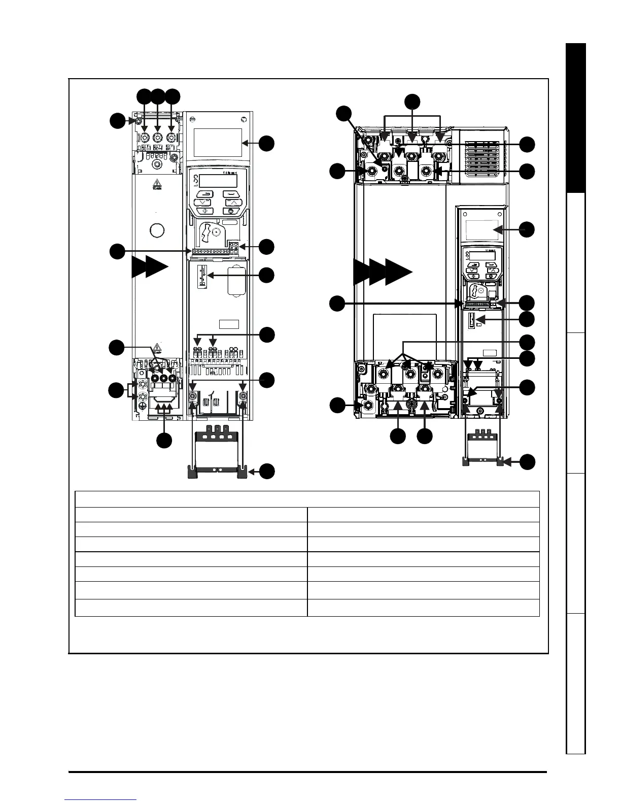
STEP 7: Identify the features of the drive
Figure 7-1 Feature diagram
Key
1. Rating label 2. Relay connections
3. Option module slot 1 4. Motor connections
5. Ground connections 6. AC supply connections
7. Control connections 8. DC bus +
9. DC bus - 10. Braking terminal
11. Cable bracket to ground terminals
12. Internal EMC filter screw
*
13. Safe Torque Off terminals (STO)**
*
Before removing the screw, refer to Chapter 4 in the Power Installation Guide.
** Unidrive M300 only.