Flash XDR User’s Manual
Left Side Connections
1. CompactFlash Slots (4): Insert (at least 1) solid-state Compact Flash card(s) face up for
record and playback.
2. CompactFlash LEDs: Compact Flash Status:
> No Light means no card inserted or the card has not been properly recognized.
> Solid green means card is OK and ready for use.
> Flashing Red means card is being written to during a record session (do not remove card).
> Flashing green means card is being read from during playback (do not remove card).
> Solid Red means the card is full (may be removed).
Right Side Connections
3. Ch. 1-2 Balanced Line Out: Analog audio output, 5-pin XLR. (See Connector Pin-Outs, page
28)
4. Mic/ Balanced Line Inputs: Analog left and right (Ch.1 and Ch.2) audio inputs.
Rear Connections
5. Power: 4-pin XLR DC power in, range +6.5V to +20V, 14 to 16 Watts; either from external
battery or included AC adapter.
6. HP Out: Unbalanced headphone audio output (3.5 mm jack). Also, headphone out provides 2
rising beeps at record start, 2 falling beeps at record stop. (ver1.5.25)
7. Remote Control: 4-pin hirose locking connector for external trigger and tally light control.
Close the switch once for record trigger and once again for record stop (see page 28 for pin-
out). Tally light flashes once a second during normal record, twice a second during record with
less than 5 minutes total record time remaining, 4 times per second with less than 1 minute
total record time remaining. (ver1.5.25)
8. RS-422/RS-485: For RS-422 based deck control and time code, external control of the Flash
XDR and for communications with external devices such as remote controls and/or laptops. (in
development)
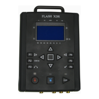
9. On/Off (Red): power button. In idle mode, the button responds immediately to turn off/ on the
unit. This button is not responsive to a brief push during a record, nor is it responsive during a
firmware update. However, holding the power button down continuously for 5 seconds at any
time will always power down the unit, regardless of the circumstances.
10. LTC In: Linear Time-Code Input.
11. 1394: 4-pin Firewire connection. Currently not operational.
12. SDI-Out: SDI only, re-clocked stream with embedded audio and time code.
13. SDI/ASI Out: SDI and ASI re-clocked output stream.
14. SDI/ASI In: SDI or ASI video source for recording.
Convergent Design, Inc 7
 Loading...