Flash XDR User’s Manual
User Connector Pin-Outs
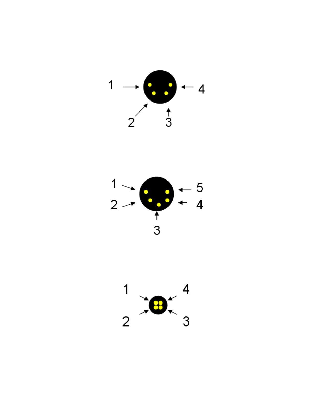
(viewed from connector on Flash XDR)
Power: 4-pin XLR
1. Ground connection 3. NC: no connect
2. NC: no connect 4. PWR: +6.5~+20V, 14 to 16 W
Audio Output: 5-pin XLR
1. GND: Signal ground
2. L+: Left channel positive 4. R+: Right channel positive
3. L-: Left channel negative 5. R-: Right channel negative
Remote Control: 4-Pin Hirose
1. START: Record trigger input 3. TALLY LED: Tally light power
2. GND 4. GND
*For your reference, the part number of the 4-pin Hirose is HR10A-7P-4S(73)*
Convergent Design, Inc 31
 Loading...