3VA/AVA/AF IO&M B51146-004
Free Discharge
Inlet Duct Turns
For ducted inlets, allow at least three fan wheel diam-
eters between duct turns or elbows and the fan inlet.
Correct
Incorrect
MIN
3 DIA
Inlet Duct Turns
Discharge Duct Turns
When possible, allow three duct diameters between duct
turns or elbows and the fan outlet.
Correct
Incorrect
MIN
3 DIA
Discharge Duct Turns
Air Flow
Small
Duct
Diverging
Inlet
Cone
Fan
Large
Duct
Air Flow
Small
Duct
Inlet
Fan
Large
Duct
Correct Incorrect
Inlet Cone
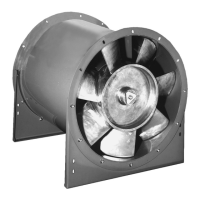
Belt and Pulley Installation
Belt tension is determined by the sound the belts make
when the fan is rst started. The belts will produce a loud
squeal, which dissipates after the fan is operating at full
capacity. If belt tension is too tight or too loose, lost e-
ciency and damage can occur.
Do not change the pulley pitch diameter to change ten-
sion. This will result in a dierent fan speed.
1. Loosen motor plate adjustment bolts and move motor plate
in order that the belts can easily slip into grooves on pulleys.
Never pry, roll or force the belts over the rim of the pulley.
2. Slide motor plate back until proper tension is reached. For
proper tension, a deection of approximately 1/4” per foot of
center distance should be obtained by rmly pressing the
belt. Refer to Figure 3.
3. Lock the motor plate adjustment nuts in place.
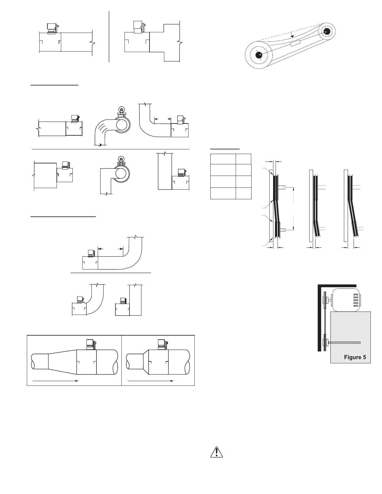
4. Ensure pulleys are properly aligned. Refer to Figure 4.
Tolerance
Center
Distance
Max.
Gap
Up through
12”
1/16”
12” up
through 48”
1/8”
Over 48” 1/4”
OFFSET ANGULAR OFFSET/ANGULAR
A
X
Y
Z
CENTER
DISTANCE
(CD)
Pulley Alignment
Pulley alignment is adjusted by loosening the motor pulley
setscrew and by moving the motor pulley on the motor shaft.
Figure 4 indicates where to mea-
sure the allowable gap for the drive
alignment tolerance. All contact
points (indicated by WXYZ) are to
have a gap less than the tolerance
shown in the table. When the pulleys
are not the same width, the allowable
gap must be adjusted by half of the
dierence in width (as shown in A &
B of Figure 4). Figure 5 illustrates us-
ing a carpenter’s square to adjust the
position of the motor pulley until the
belt is parallel to the longer leg of the square.
Wiring Installation
Leave enough slack in the wiring to allow for motor move-
ment when adjusting belt tension. Some fractional motors
have to be removed in order to make the connection with
the terminal box at the end of the motor. To remove motor,
remove bolts securing motor base to power assembly. Do
not remove motor mounting bolts.
NOTICE! Follow the wiring diagram in the discon-
nect switch and the wiring diagram provided with
the motor. Correctly label the circuit on the main
power box and always identify a closed switch to
promote safety (i.e., red tape over a closed switch).
Figure 3
Figure 4
 Loading...