4VA/AVA/AF IO&M B51146-004
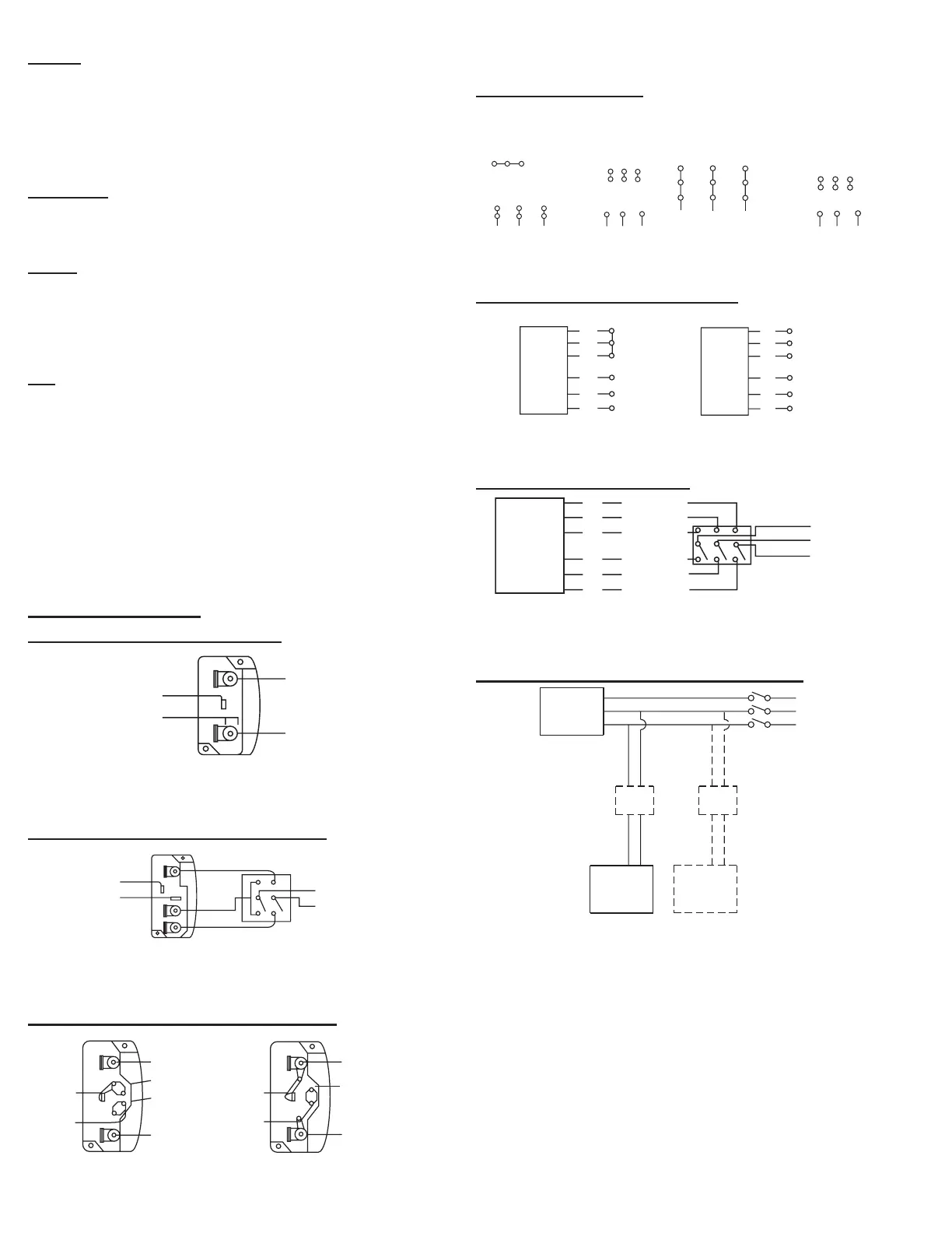
When ground is required, attach to ground A or B with No. 6
thread forming screw. To reverse, interchange T-5 and J-10 leads.
3-Phase, 9 Lead Motor
4
5
6
1
7
2
8
3
9
L
1
L
2
L
3
456
7
8
9
12
3
L
1
L
2
L
3
Low Voltage
230 Volts
High Voltage
460 Volts
3 Phase, 9 Lead Motor
Y-Connection
7
1
6
789
4
5
6
12
3
Low Voltage
230 Volts
High V
460 Volts
8
2
4
9
3
5
L
L
L
L
1
L
3
L
2
3 Phase, 9 Lead Motor
Delta-Connection
To reverse, interchange any 2 line leads.
2 Speed, 1 Winding, 3-Phase Motor
Motor
1
2
3
4
5
6
Together
Line
L
1
L
2
L
1
2
3
4
5
6
Open
L
1
L
2
L
3
Motor
To reverse, interchange any 2 line leads. Motors require magnetic
control.
2 Speed, 2 Winding, 3-Phase
L
1
T
1
T
2
T
3
Low Speed
Low Speed
Low Speed
High Speed
High Speed
High Speed
Motor
T
13
T
12
T
11
L
2
Line
L
3
To reverse: High Speed: interchange leads T
11
and T
12
. Low
Speed: interchange leads T
1
and T
2
. Both Speeds: interchange
any 2 line leads.
Typical Fan Motor/Damper Motor Schematic
Fan
Motor
Damper
Motor*
Second
Damper
ansformer**
Transformer*
L3
L2
L1
For 3-Phase, damper motor voltage should be the same be-
tween L
1
and L
2
. For single phase application, disregard L
3
.
*Damper motors may be available in 115, 230 and 460 volt mod-
els. The damper motor nameplate voltage should be veried pri-
or to connection.
**A transformer may be provided in some installations to correct
the damper motor voltage to the specied voltage.
Use of Variable Frequency Drives
Motors
Motors that are to be operated using a Variable Fre-
quency Drive (VFD) must be VFD compatible. At a mini-
mum, this must be a Premium Eciency motor with Class
F insulation. Motors that are not supplied by Loren Cook
Company should have the recommendation of the motor
manufacturer for use with a VFD.
Grounding
The fan frame, motor and VFD must be connected to a
common earth ground to prevent transient voltages from
damaging rotating elements.
Wiring
Line reactors may be required to reduce over-voltage
spikes in the motors. The motor manufacturer should be con-
sulted for recommended line impedance and usage of line
reactors or lters if the lead length between the VFD and the
motor exceeds 10 ft (3m).
Fan
It is the responsibility of the installing body to perform
coast-down tests and identify any resonant frequencies after
the equipment is fully installed. These resonant frequencies
are to be removed from the operating range of the fan by us-
ing the “skip frequency” function in the VFD programming.
Failure to remove resonant frequencies from the operating
range will decrease the operating life of the fan and void the
warranty.
Please refer to AVA Critical Fan Speed, page 5. Variable
frequency drives should not allow AVA fans to operate be-
tween the low and the high speeds list.
Wiring Diagrams
Single Speed, Single Phase Motor
T-1
4
L
2
L
1
When ground is required, attach to ground A or B with No. 6
thread forming screw. To reverse, interchange T-1 and T-4.
2 Speed, 2 Winding, Single Phase Motor
T-1
4
Low Speed
High Speed
L
1
L
2
When ground is required, attach to ground A or B with No. 6
thread forming screw. To reverse, interchange T-1 and T-4 leads.
Single Speed, Single Phase, Dual Voltage
T-5
Link A
Link B
Low Voltage
Line
L
2
L
1
Link A
and B
L
1
L
2
T-5
J-10
 Loading...