5VA/AVA/AF IO&M B51146-004
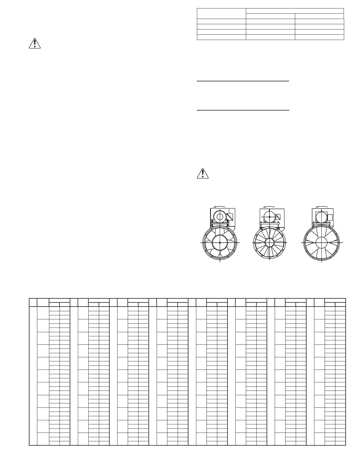
AVA Critical Fan Speed (the AVA should not operate between the high and low RPM)
Fan
Size
Blade
Angle
Fan RPM
Fan
Size
Blade
Angle
Fan RPM
Fan
Size
Blade
Angle
Fan RPM
Fan
Size
Blade
Angle
Fan RPM
Fan
Size
Blade
Angle
Fan RPM
Fan
Size
Blade
Angle
Fan RPM
Fan
Size
Blade
Angle
Fan RPM
Fan
Size
Blade
Angle
Fan RPM
Low High Low High Low High Low High Low High Low High Low High Low High
35
10
600 615
39
10
370 385
44
10
525 535
49
10
315 320
57
10
330 340
63
10
215 225
71
10
250 265
79
10
250 265
900 925 565 580 790 800 460 470 500 540 325 340 370 400 370 400
1820 1865 1135 1165 1590 1615 935 950 1005 1025 660 680 750 805 750 805
13
615 630
13
375 390
13
525 535
13
320 325
13
335 345
13
220 230
13
250 265
13
250 265
920 945 570 585 790 805 465 475 510 520 330 340 375 400 375 400
1860 1910 1150 1180 1595 1620 940 955 1015 1035 665 680 755 810 755 810
16
625 645
16
380 395
16
795 805
16
320 325
16
340 350
16
220 230
16
250 270
16
250 270
940 965 575 590 530 535 465 475 520 530 330 345 380 400 380 400
1895 1950 116 0 119 5 1600 1625 945 960 1020 1045 665 685 760 810 760 810
19
635 655
19
385 400
19
795 810
19
320 325
19
340 350
19
220 230
19
255 270
19
255 270
955 980 580 600 530 540 470 480 520 525 330 345 380 405 380 405
1925 1980 1175 1210 1605 1630 950 970 1025 1050 670 685 765 815 765 815
22
645 660
22
390 405
22
530 540
22
320 325
22
340 350
22
220 230
22
255 270
22
255 270
965 995 585 605 800 810 470 480 520 535 330 345 385 405 385 405
1950 2005 1185 1220 1615 1635 955 975 1035 1060 670 690 770 820 770 820
25
650 670
25
390 410
25
535 545
25
320 325
25
340 350
25
225 235
25
255 270
25
255 270
975 1005 590 610 805 815 475 485 525 540 330 350 385 405 385 405
1970 2050 119 5 1230 1620 1645 960 980 1040 1065 675 695 775 820 775 820
28
655 675
28
395 410
28
535 545
28
325 330
28
345 355
28
225 235
28
260 270
28
260 270
985 1010 595 615 805 820 475 490 525 540 335 350 385 410 385 410
1980 2040 1205 1240 1625 1650 970 985 1050 1070 675 700 780 825 780 825
31
655 675
31
400 415
31
540 550
31
325 330
31
345 355
31
225 235
31
260 275
31
260 275
985 1015 600 620 810 825 480 495 525 540 335 350 390 410 390 410
1990 2045 1215 1250 1635 1660 975 990 1055 1070 680 700 785 825 785 825
34
660 675
34
400 420
34
540 550
34
325 335
34
350 360
34
225 235
34
260 275
34
260 275
990 1015 605 625 815 825 485 500 525 540 340 350 390 410 390 410
1995 2045 1220 1250 1640 1670 980 1000 1060 1075 685 700 790 830 790 830
37
660 675
37
405 420
37
545 555
37
325 335
37
350 360
37
225 235
37
260 275
37
260 275
990 1010 610 625 815 830 485 500 525 540 340 350 395 410 395 410
1995 2040 1225 1250 1650 1675 985 1005 1065 1080 690 705 795 830 795 830
40
655 670
40
410 420
40
545 555
40
325 340
40
350 360
40
225 235
40
265 275
40
265 275
985 1005 615 625 820 835 490 500 525 540 340 350 395 415 395 415
1990 2030 1230 1245 1655 1685 995 1010 1070 1085 695 705 795 835 795 835
Bolt Size
Torque (FT- LB)*
Minimum Maximum
5/8”
40 110
3/4”
140 190
7/8”
265 350
1”
450 550
*For adjustment of blades only.
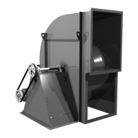
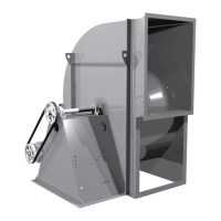
Propeller Rotation
Test the fan to ensure the rotation of the wheel is the
same as indicated by the arrow marked Rotation.
115 and 230 Single Phase Motors
Fan wheel rotation is set correctly at the factory. Chang-
ing the rotation of this type of motor should only be at-
tempted by a qualied electrician.
208, 230 and 460 3-Phase Motors
These motors are electrically reversible by switching two
of the supply leads. For this reason, the rotation of the fan
cannot be restricted to one direction at the factory. See
Wiring Diagrams, page 4, for specic information on re-
versing wheel direction.
NOTICE! Do not allow the fan to run in the wrong
direction. This will overheat the motor and cause
serious damage. For 3-phase motors, if the fan is
running in the wrong direction, check the control
switch. It is possible to interchange two leads at
this location so that the fan is operating in the cor-
rect direction.
Rotation
VAB/VAHB
Rotation
AVAB
*Rotation
AFB
Prop Side Prop Side Prop Side
*Size 54 & 60
rotation is opposite.
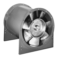
Blade Angle Adjustment
Instructions for adjusting blade angle setting on adjust-
able pitch vane Axial Inline Blowers (AVA):
NOTICE! Verify that the fan at the new pitch does
not operate at a critical speed (RPM) see table be-
low.
WARNING: The maximum safe blade angle setting for
this fan is shown on the decal located inside the hub
cover.
1. Disconnect power supply.
2. Remove hub cover.
3. Placing a bubble protractor on the at machined sur-
face on the discharge side of the hub, take an initial
reading. When setting the blade to the desired angle
(no greater than 40°), remember to allow for the angle
at which the fan is installed, as indicated by the initial
reading.
4. Adjust each blade individually as follows (note that one
person should hold and adjust the blade while another
tightens the nuts).
5. Place blade in 3 o’clock or 9 o’clock position.
6. Loosen retaining nut on blade bolt.
7. Position bubble protractor on the face (discharge side)
of the blade at the indicated line, If the line is not vis-
ible, position protractor on a line perpendicular to the
blade center line, and 30% of the wheel radius in from
the tip on 39”, 49”, 63” and 79” fans (33% on 35”, 44”
55” and 71” fans).
8. Set blade to desired angle, correcting for angle of
installation.
9. Tighten nut so that blade is snug.
10. Recheck blade angle. If blade has shifted, tap blade
near hub with soft mallet to correct.
11. Tighten nut to tabulate torque (see following Torque
chart).
12. Rotate wheel to bring next blade into same position
and repeat steps 5-12 until all blades are adjusted.
13. Replace hub cover.
14. Reconnect power supply.
 Loading...