(continued from previous page)
A. Press the MENU button on the front panel.
B. Using the down arrow key, navigate to the BATTERY
menu, and press ENTER.
C. Using the down arrow key, navigate to the TEST
BATTERY menu and press ENTER.
D. Press the F4 button to test the battery.
Note: This message will appear on the programming
panel LCD display: ----TESTING----
The battery test results will display in the battery
metering menu.
Note: Voltage should be between 25–31 VDC – with the
higher voltage at colder temperatures.
Under normal conditions, with AC connected and
a fully charged battery, the charging current
should be less than 20 mA.
With AC connected and a discharged battery, the
current range should be 20–450 mA.
With AC disconnected and the battery supplying
the load, current will read -400 to -600 mA
depending on accessories connected.
4. Verify the Control OK LED is illuminated on the control
operator panel (Figure 28). This indicates the presence
of AC power.
Note: The control includes a Power Save feature that will
turn off the backlit LCD display and all LEDs if no
front panel keypad is pressed within ten minutes.
Pressing the LAMP TEST key will reactivate the dis-
play and active LEDs.
All other tests described in this TESTING section require
the Form 6-LS control to be removed from service, con-
nected to a bypassed recloser, or tested at a location
where the proper testing equipment is available.
Remove the Control from Service
1. Enable GND TRIP BLOCKED to allow for ground trip to
be disabled when re-energized.
A. Press the CHANGE button on the Operator Panel to
enter the CHANGE mode.
B. Depress the GND TRIP BLOCKED button within ten
seconds after entering the CHANGE mode.
Note: If the GND TRIP BLOCK button is not pressed
within ten seconds, the function is not activated.
2. Disconnect the battery.
3. Remove control AC sensing and power connections
from the control using a separate disconnect switch.
4. Disconnect control cable from control.
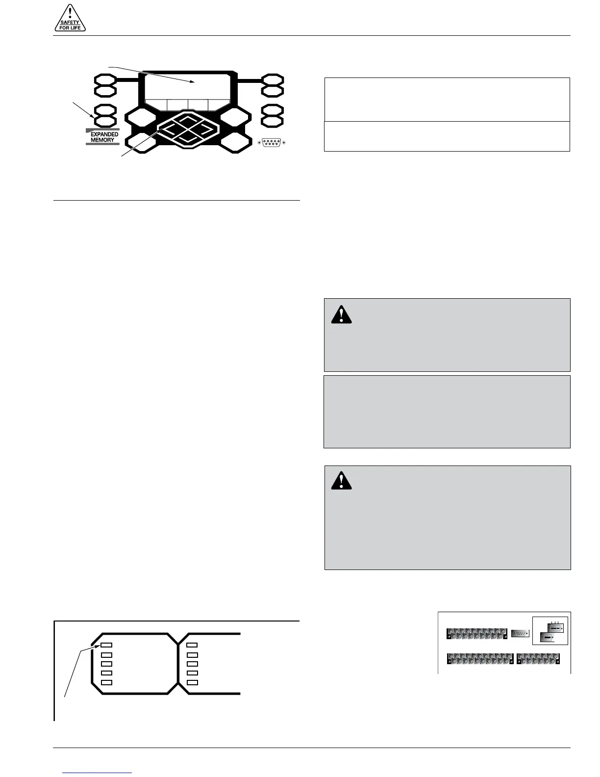
5. Remove any control input and status output wiring
from TB1, TB3, and TB4 (Figure 29).
6.
Disconnect any serial
communications ports
and IRIG-B timing con-
nections (Figure 29).
7. Disconnect the ground
from the control.
8. Carefully transport the
control to a suitable
service facility.
S280-70-10
37
CONTROL POWER
CONTROL OK
CONTROL LOCKOUT
RECLOSER OPEN
RECLOSER CLOSED
A PHASE FAULT
B PHASE FAULT
C PHASE FAULT
GROUND FAULT
SENSITIVE GND
Control OK LED
Figure 28.
Control OK LED.
METERING
RESET
TARGETS
EVENTS
LAMP TEST
MENU
ENTER
+
—
SETTINGS
OPER
COUNTER
ALARMS
CHANGE
F1 F2 F3 F4
RS-232 DATA PORT
LCD Display
LAMP TEST Key
Cursor Movement
Arrows
Figure 27.
Lamp Test button, LCD display, and cursor movement
arrows.
IIMPORTANT: Disconnect switches for AC sensing
and power connections are necessary to isolate the
Form 6 control for testing and servicing.
IMPORTANT: The control must be removed from ser-
vice in the exact order specified in this section.
CAUTION: Equipment misoperation. Disconnect all
control power sources prior to disconnecting or recon-
necting the control cable from the control. Failure to
comply can result in recloser misoperation at the time of
disconnection or reconnection of the control cable to the
control. T311.1
CAUTION: Hazardous voltage. Open CT sec-
ondaries can generate high voltages. Contact
with CT pins of the disconnected cable can cause elec-
tric shock and may result in personal injury. Open
recloser contacts and open disconnect switches before
disconnecting control cable. T204.3
CAUTION: Hazardous voltage. Cable conductors
attached to controls will remain at 53 VDC and
120 VAC potential while connected to the control.
Contact with any pins at the end of the cable directly or
indirectly connected to a control can result in personal
injury or equipment damage. Disconnect battery and
external power sources in the control then remove
control cable at control end before disconnecting from
recloser end. T312.2
TB1
1
2
3 57911 13 15 17 19
46 81012141618
CI1
CI2 CI3 SS1 CO1
CO2 CO3
CO4
CI4
CI1 CI2 CI3 SS1 CO1 CO2 CO3 CO4
TB3
1
3
579111315171921
CI5 CI6 CI7 CI8 CI9 CI10 CI11 CO5 CO6
TB4
2
46 81012141618
20
CI4 CI5 CI6 CI7 CI8 CI9 CI10 CI11 CO5
CO6
13
5
7911 13
CO7CO8
CO9CO10CO11
CO12
2
46 81012
CO7CO8 CO9CO10CO11CO12
J1-RS-232
IRIG-B
RS-485
RS-232 DTE
C + –
Figure 29.
Back view of top half of Form
6-LS recloser control.