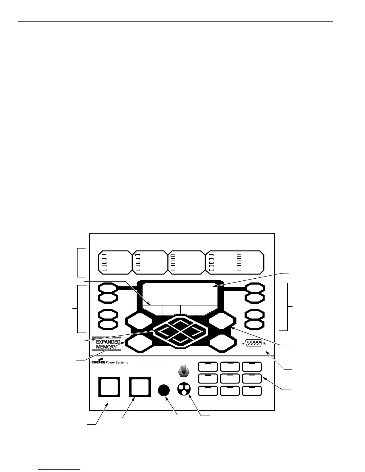
Control Front Panel
The Form 6-LS control front panel is illustrated in Figure 4.
The front panel is separated into two clearly identified,
color-coded sections:
• The top portion of the front panel is used for programming
the control and providing LED status indication.
• The lower portion of the front operating panel is used
for operating the control and recloser.
The control includes a Power Save feature that will turn off
the backlit LCD display and all LEDs (except Hot Line Tag)
if no front panel keypad is pressed within ten minutes.
Pressing the LAMP TEST key will re-activate the display
and LEDs.
Note: The Power Save feature is a ProView interface software
default setting. This feature can be disabled via the
ProView interface software.
The control includes a Reset Menu feature that will cause
the LCD display to revert to the root menu after ten minutes
of inactivity.
Note: The ten minute timer and MMI Reset Menu is a ProView
interface software default setting. The menu selection
and timer can be changed via the ProView interface
software.
Front Panel Text Messaging
The LCD messages are accessed from the front panel by
following the Text Messages menu path. This menu
displays any active user-configured text messages.
Up to fourteen user-configurable text messages can be
programmed via the Idea Workbench. Refer to Service
Information S280-70-4 (ProView 4.X.X) or S280-70-21
(ProView 5.X.X) Form 6 Control Programming Guide for
information on programming the text messages.
These text messages appear on the front panel LCD and
can be programmed to appear for alarm or other
conditions.
Text messages displayed on the front panel are limited to
four lines of 20 characters each (including spaces). Text
messages can also be accessed by pressing the LAMP
TEST one-touch analysis key on the front panel.
Form 6-LS Pole Mount Recloser Control Installation and Operation Instructions
6
CONTROL POWER
CONTROL OK
CONTROL LOCKOUT
RECLOSER OPEN
RECLOSER CLOSED
A PHASE FAULT
B PHASE FAULT
C PHASE FAULT
GROUND FAULT
SENSITIVE GND
ALARM
ABOVE MIN TRIP
TIE
SECTIONALIZER
LS DISABLED
A PHASE VOLTAGE
B PHASE VOLTAGE
C PHASE VOLTAGE
FREQUENCY TRIP
VOLTAGE TRIP
METERING
RESET
TARGETS
EVENTS
LAMP TEST
MENU
ENTER
+
—
SETTINGS
OPER
COUNTER
ALARMS
CHANGE
F1 F2 F3 F4
TRIP CLOSE
HOT LINE TAG
ON
GRD TRIP
BLOCKED
NON
RECLOSING
SUPERVISORY
OFF
LS RESET
SOURCE I
ENABLED
SOURCE II
ENABLED
F6 Recloser Control
RS-232 DATA PORT
OPTION#1 OPTION #2 OPTION#3
(LOCKOUT)
X PHASE VOLTAGE
Y PHASE VOLTAGE
Z PHASE VOLTAGE
INDICATOR 7
INDICATOR 8
LCD Display
LCD Display
Dedicated
Function Keys
One-Touch
Analysis Keys
Hot Line Tag Toggle Switch and
Three-Segment LED Indication
RS-232
Configuration
Data Port
CLOSE Pushbutton
TRIP (LOCKOUT)
Pushbutton
LED Indicators
LCD Display
Dedicated
Function Keys
One-Touch
Function Keys
Cursor Movement Arrows
LCD Menu Function Keys
One-Touch
Analysis Keys
Close Circuit
Disable Fuse
and Fuseholder
CLOSE CIRCUIT
DISABLE
Figure 4.
Form 6-LS control front panel.
 Loading...