Return the Control to Service
After the required work is completed, disconnect the con-
trol from the test set and follow this procedure to return the
control to service:
1. While still in service shop, appropriate personnel must
verify that all control settings are correct.
2. Reconnect the ground cable to the control.
3. Control cable properly connected and supported.
4. Plug in the control battery.
Note: The Form 6-LS control will not power up until AC
power is applied.
5. Verify the selector switch on the Power Supply/Battery
Charger Board is set to the 115V position for 120 VAC
incoming power.
6. Apply AC power to the control.
Note: In the event of loss of AC control power to the control
(without battery back-up power), the LS control will
reset to the following conditions when power is
restored to the control:
• In the TIE Mode, once voltage is restored, the LS is
disabled until locally or remotely enabled. This is to
ensure that the TIE recloser will not close automati-
cally upon restoration of voltage from one source.
• In the SECTIONALIZING mode, once voltage is
restored, the LS is disabled until locally or remotely
enabled. The control remains in the present state
prior to the loss of voltage. The SECTIONALIZING
unit will not close automatically.
Note: LS must be enabled via the ProView interface soft-
ware Loop Scheme Settings Dialog screen located in
the Idea Workbench.
7. Disable GND TRIP BLOCKED.
A. Press the CHANGE button on the Operator Panel to
enter the CHANGE mode.
B. Depress the GND TRIP BLOCKED button within ten
seconds after entering the CHANGE mode.
Note: Once selected (or after ten seconds), the control
returns to normal operation.
8. Verify the control clock is set to the current time after
AC power has been reapplied.
Note: The control clock may require resetting if the
operating power has been disconnected for more
than thirty days. Refer to ServiceInformationS280-
70-4(ProView4.X.X)orS280-70-21(ProView5.X.X)
Form 6 Microprocessor-Based Recloser Control
Programming Guide for information on setting the
control clock.
.
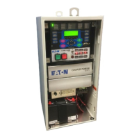
Form 6-LS Pole Mount Recloser Control Installation and Operation Instructions
44
CAUTION: Equipment damage Form 6-LS (Loop
Scheme). Do not connect 240 VAC to B or Y phases on
terminal blocks TB7 or TB8. 240 Volts will damage inter-
nal components and cause control misoperation.
T314.0
CAUTION: Equipment misoperation. Verify that
the 120/240 VAC selector switch is correctly set
for incoming voltage. Failure to comply may cause
misoperation (unintentional operation) of the control
and/or equipment damage resulting in personal injury.
T278.0
CAUTION: Equipment misoperation. Do not
connect this control to an energized recloser until
all control settings have been properly programmed and
verified. Refer to the programming information for this
control. Failure to comply can result in control and
recloser misoperation, equipment damage, and per-
sonal injury. G110.3
CAUTION: Equipment misoperation. Disconnect all
control power sources prior to disconnecting or recon-
necting the control cable from the control. Failure to
comply can result in recloser misoperation at the time of
disconnection or reconnection of the control cable to the
control. T311.1
IMPORTANT: Prior to reconnecting the control cable,
verify the control was removed from service in the exact
order specified in the Remove the Control from
Service section of this manual.
 Loading...