Form 6-LS Pole Mount Recloser Control Installation and Operation Instructions
38
Preliminary Testing with No AC
Available
If the Form 6 control is not in service and requires
energization for preliminary testing, it can be powered up
with battery power only.
Note: Controls with expanded memory require battery voltage
to be 23VDC minimum.
1. Open the rear door of the Form 6 pole-mount control
cabinet and locate terminals TM1 and TM2 on the
power supply circuit board (Figure 30).
2. Momentarily jumper terminals TM1 and TM2 together.
(The control will power up.)
3. To power down the Form 6 control, unplug the battery
(disconnect the black/red battery connector).
4. Perform a battery charging cycle. Refer to Battery
Charging in the Battery Test and Charging
Procedures section of these instructions.
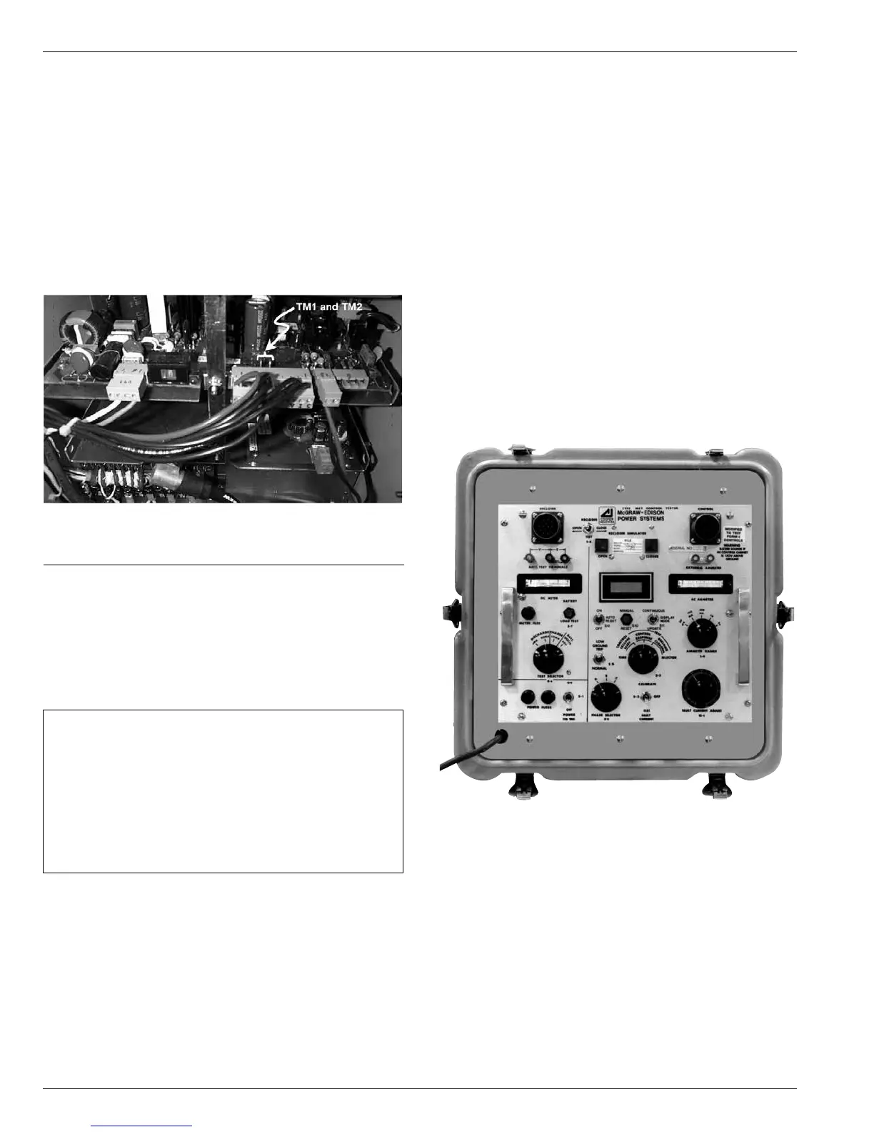
Testing with Type MET Tester
The Type MET electronic recloser control tester (Figure 31)
is used for testing the following functions of the Form 6
recloser control:
• Overcurrent Timing
• Reclose Time
• Operating Sequence
• Reset Time
• Minimum Trip Current
• High Current Trip and Lockout
The MET Tester is completely self-contained, capable of
performing all required checks and tests from a simple
verification of operation to a complete verification of all
operating parameters.
Refer to Service Information S280-76-1 Type MET
Electronic Recloser Control Tester Operating Instructions
for proper setup and use of the MET Tester.
Figure 31.
Type MET electronic recloser control tester.
IMPORTANT: While the Form 6 control is powered in
this manner, the control battery is being continuously
discharged. When the battery voltage drops to 22V DC,
the control will automatically power down.
If the battery is left in a discharged condition, the
battery(s) will sustain permanent irreversible damage.
Therefore, a battery charging cycle should always be
performed after this procedure to bring the battery(s)
back up to full charge.
Figure 30.
Location of terminals TM1 and TM2 on the power
supply circuit board