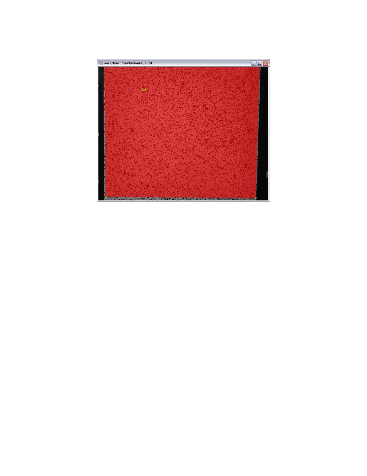
Load this image pair as the Reference image, as normal. Define an area of interest that contains the two measurement
marks and encompasses as much of the shape as possible. Using a patch that is too narrow or small may result in erroneous
results. Our two “X” marks are visible about halfway down the image.
Define an initial guess if needed, ang click Start analysis. Since no Transformation calibration is present, you will be
prompted to run a disparity analysis for calibration. Click Yes; this sets all the appropriate options for this type of
calibration. Click Run to continue, then Close when correlation is complete. Projection error will be reported as 0, and no
3D plot will be shown; this is because Vic-3D has no geometry information with which to triangulate a shape. However,
we’ve just calculated the raw disparities, which can now be used to determine the camera orientation.
 Loading...