65
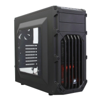
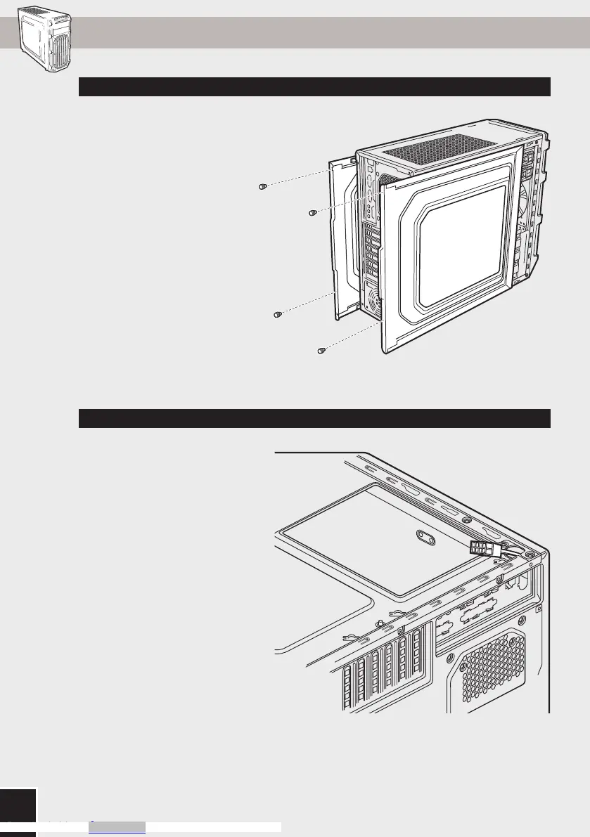
3. Installing the Motherboard1. Removing the Side Panels
SPEC-03
Simply remove the
thumbscrews then slide the
side panels back and out.
Note: Corsair recommends
removing both side panels and
setting them aside when building
your system to avoid accidental
damage. Both side panels are
interchangeable and should be
removed to reduce clutter.
First, install your
motherboard’s I/O shield (see
your motherboard’s manual
for guidance).
Align your motherboard with
the pre-installed standos.
Use the provided screws
to secure the motherboard to
the motherboard tray.
Remove thumbscrews and
corresponding slot cover(s).
Install the add-on card and
secure with thumbscrews.
To install your flat CPU 8/4 pin
cable, route the cable through
the motherboard tray before
installing the motherboard.
Only Flat Cables will be
compatible and you must split
your cable into 2 pieces to fit
through the cutout.
2. Utilizing the CPU power cable cut-out 4. Installing the PCI-E/PCI card(s)
b
carbide spec-03
STEP 03 / ps
1
2
Downloaded from Arrow.com.Downloaded from Arrow.com.Downloaded from Arrow.com.Downloaded from Arrow.com.Downloaded from Arrow.com.

 Loading...