EasyManuals Logo

Corsair Carbide series Installation Guide

Corsair Carbide series
51 pages
To Next Page IconTo Next Page
To Previous Page IconTo Previous Page
Page #7 background imageLoading...
Page #7 background image
109
ENGLISH
SPEC-03
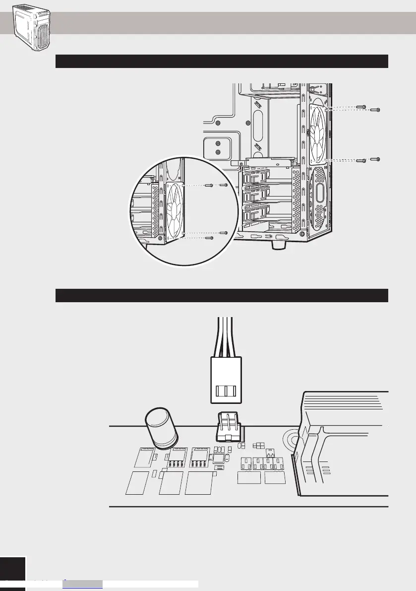
11. Installing the Front I/O Connectors9. Installing a Second Front Fan
10. Powering the Case Fans
After locating your 3 or 4
pin fan headers on your
motherboard (see your
motherboard’s manual for fan
header locations), plug in the
included fan cable.
See your motherboard’s
manual for front panel header
locations and pin-outs.
USB 3.0
HD AUDIO RESET SW
POWER LED +
POWER LED POWER
SW
HDD LED
To install an additional 120mm
or 140mm fan, unscrew the
top fan then slide it down to
the mounting points below.
carbide spec-02
STEP 08
carbide spec-02
STEP 08
Downloaded from Arrow.com.Downloaded from Arrow.com.Downloaded from Arrow.com.Downloaded from Arrow.com.Downloaded from Arrow.com.Downloaded from Arrow.com.Downloaded from Arrow.com.

Table of Contents

Other manuals for Corsair Carbide series

Questions and Answers:

Question and Answer IconNeed help?

Do you have a question about the Corsair Carbide series and is the answer not in the manual?

Corsair Carbide series Specifications

General IconGeneral
TypeMid Tower
Motherboard SupportATX, Micro-ATX, Mini-ITX
MaterialSteel, Plastic
Expansion Slots7
Front I/O Ports1 x Headphone, 1 x Microphone
Radiator Support120mm rear
Drive Bays2 x 2.5", 2 x 3.5"

Related product manuals