87
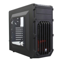
SPEC-03
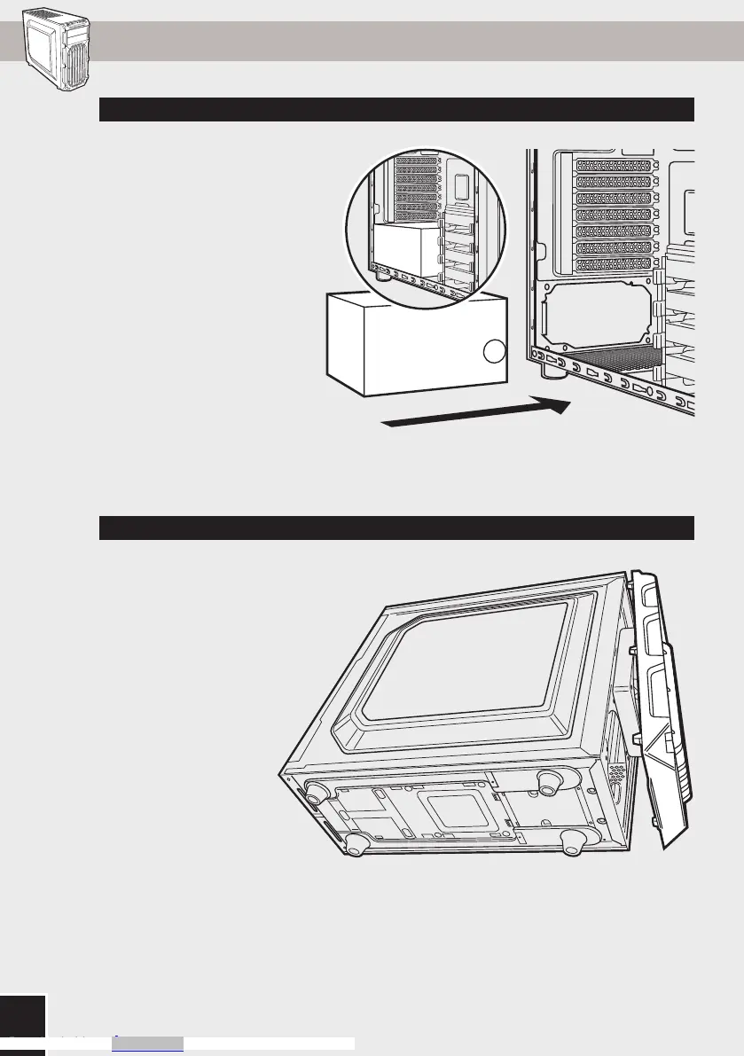
7. Installing an ODD (Optical Disk Drive)5. Installing the PSU (Power Supply Unit)
6. Removing the Front Fascia 8. Installing SSDs and HDDs
To remove the front fascia
(front panel), grasp the tab
located at the bottom fascia
and pull outward.
First, remove the front panel
5.25" drive bay cover then
slide the ODD into the drive
bay until the tool-free latch
clicks, securing the drive. To
release an optical drive, push
in the tool-free tab then pull
the drive outward.
Simply pull back retention arm
and slide in the 2.5" SSD or
3.5" HDD until the retention
arm snaps back into place.
Position the PSU on the
bottom of the case then align
the case holes and secure the
PSU with screws provided with
your power supply.
carbide spec-03
STEP 06 / sl
carbide spec-03
STEP 06 / sl
First
Second
Downloaded from Arrow.com.Downloaded from Arrow.com.Downloaded from Arrow.com.Downloaded from Arrow.com.Downloaded from Arrow.com.Downloaded from Arrow.com.

 Loading...