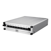
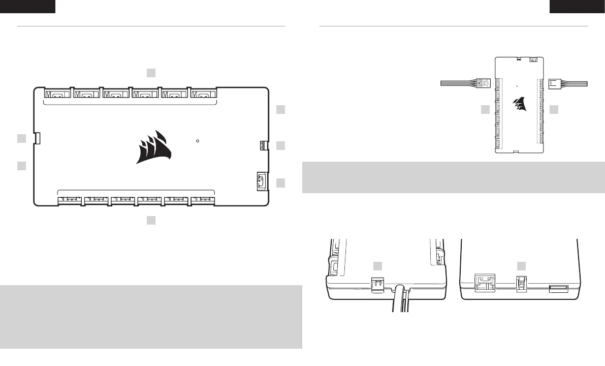
GETTING TO KNOW iCUE COMMANDER CORE XT INSTALLATION
A — 4-pin PWM fan headers
B — 4-pin RGB hub
C — 3-pin RGB header
D — Thermistor header
E — ID header
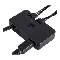
F — SATA power and USB cable
NOTICE: Turn your computer off prior to installing your COMMANDER CORE XT. Find a location for the
COMMANDER CORE XT that allows connection for all the fan cables installed in your computer
to reach the COMMANDER CORE XT.
NOTE: 4-pin PWM fan speed can be fully controlled through CORSAIR iCUE software. 3-pin fans plugged into the
COMMANDER CORE XT will operate at their rated full speed.
TIP: The thermal sensors are designed to measure ambient temperatures, so for the most accurate results, they should not
directly touch components. You may find it useful to mount the thermal sensors near air intake and exhaust points, and
if your PC case has multiple compartments, you can try placing each of the sensors in its own compartment. Since the
thermal sensors can easily be repositioned, you can try various locations and use what works best for you.
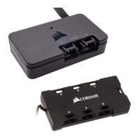
CONNECT FANS TO COMMANDER CORE XT
> Connect the 4-pin fan and 4-pin RGB
headers into the “FANS (A)” and “RGB HUB
(B)” headers respectively.
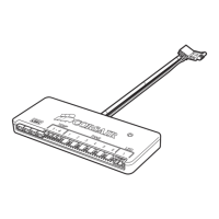
CONNECT THE THERMAL SENSORS INTO THE 2-PIN “TEMP (D)” HEADERS
65 4 3 2 1
FANS
RGB
TEMP 2
TEMP 1
ID
65 4 3 2 1
RGB HUB
65 4 3 2 1
FANS
RGB
TEMP 2
TEMP 1
ID
65 4 3 2 1
RGB HUB
B
E
D
D
F
C
A
D D
B A
21
ENGLISH ENGLISH
 Loading...