10
CABINET MOUNTING
1. Locate the knockout on the right side of the furnace to mount
the thermostat. Remove the knockout by tapping it lightly
with a screwdriver.
2. Cut the thermostat wire to the required length below.
Model Number Length
CDV14 Series 31 inches
CDV22 Series 45 inches
CDV30 Series 47 inches
3. Connect the thermostat wires to terminal screws on the
front of the thermostat base. See instructions packaged
with thermostat.
4. Feed the thermostat wires through the knockout and to
he gas valve.
IMPORTANT: Keep the thermostat wire away from the
combustion chamber.
5. Mount the thermostat to the side of cabinet with the
screws provided. Replace the thermostat cover.
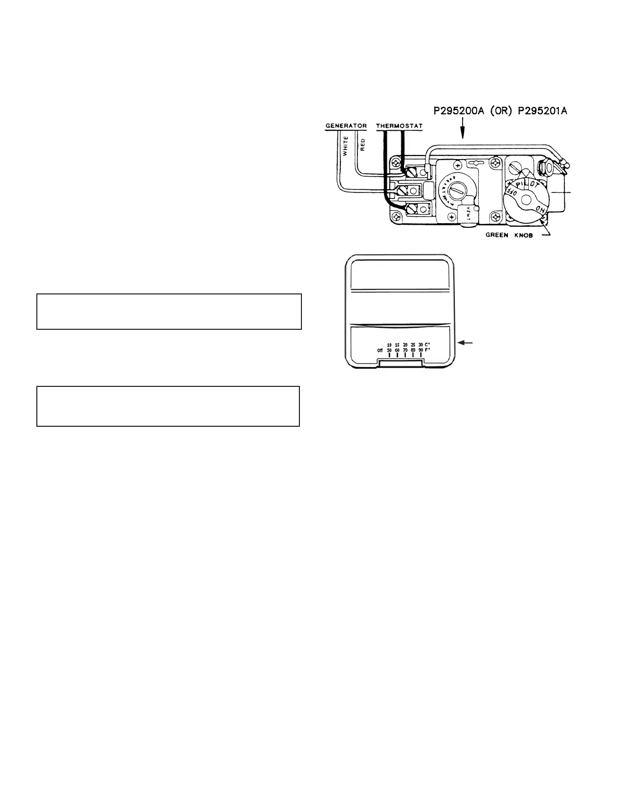
6. Connect the thermostat wire to the gas valve. Figure 9
IMPORTANT: BEFORE REMOVING THE FACE PANEL
DISCONNECT THERMOSTAT WIRES AT THE GAS VALVE.
Thermostat Mounting
1. To remove the thermostat cover, grasp cover and squeeze
both sides rmly, then lift to remove cover. Carefully
remove and discard the packing tab protecting the
switch contacts.
2. Connect thermostat wires to the terminal screws on the
front of thermostat base.
3. Push any excess wire back through hole in the wall and
plug the hole with insulation to prevent drafts from
aecting thermostat operation.
4. Being sure to level thermostat for the best appearance.
Fasten the thermostat base to the wall through the
mounting holes with the screws provided.
5. Replace the thermostat cover.
NOTE: Refer to the installation instructions packed in the thermostat
carton if you have any doubt about the above procedures.
FIGURE 9
SQUEEZE FIRMLY
BOTH SIDES AND
LIFT TO REMOVE
COVER
Cabinet Installation
CDV14 SERIES:
Set the cabinet over the furnace body, dropping the rear top ange
between the support legs and wall. Open the cabinet door and attach
the cabinet to the inner casing with two (2) sheet metal screws.
Figure 10
CDV22 / CDV30 SERIES:
Set the cabinet over the furnace body, dropping the rear top ange
into the slot in top of the spacer plate and into the slots between
the support legs and wall. When correctly positioned side-to-side,
a dimple on the rear top ange will slide against the inside of each
support leg. Attach two (2) tension springs through the bottom ange
of the combustion chamber and the bottom of the cabinet. Fasten the
trim strip to the bottom of the support legs using two (2) sheet metal
(short) screws. Figure 11