DIRECT VENT GRAVITY GAS WALL HEATER 17
CARING FOR YOUR FURNACE
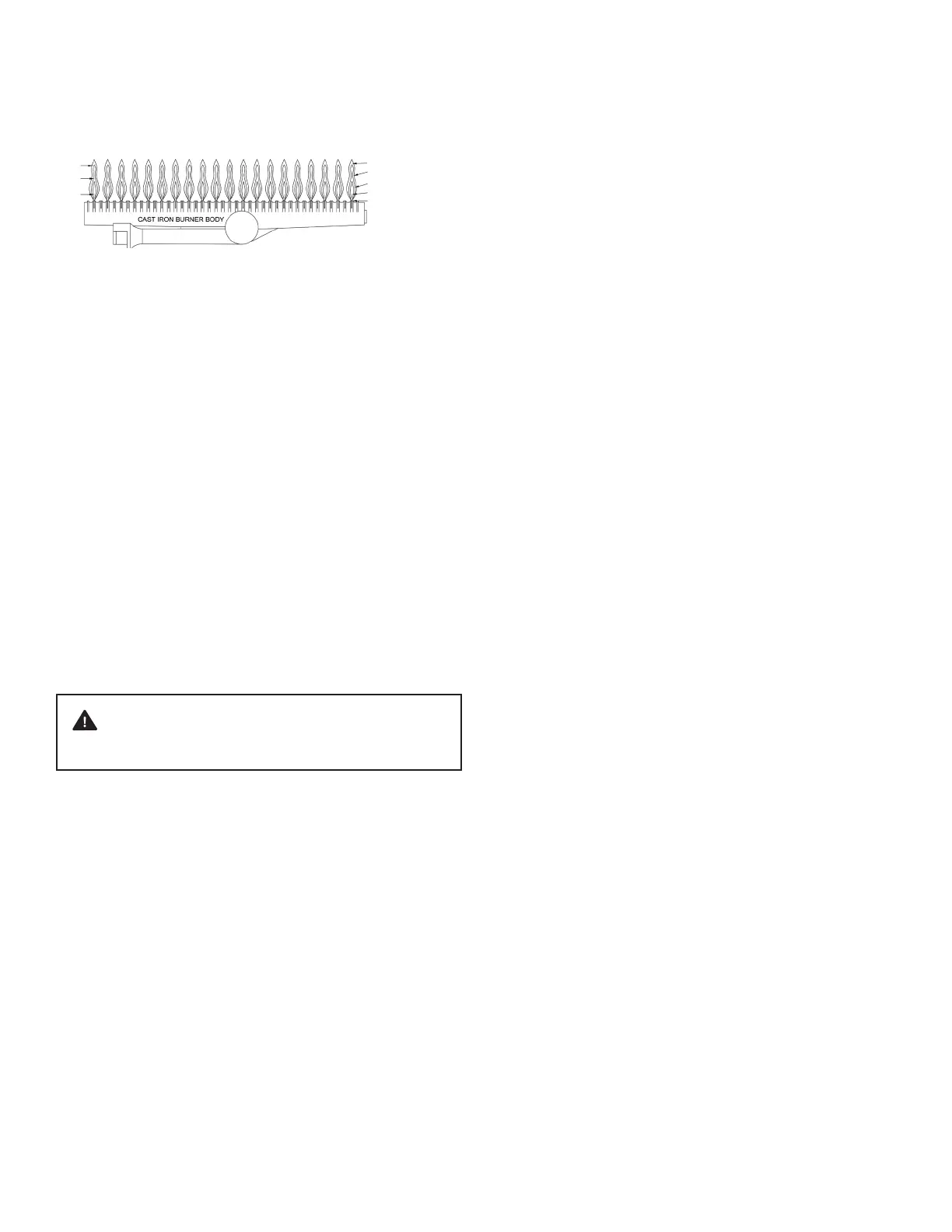
NORMAL APPEARANCE NATURAL GAS:
1. Inner cone- blue color - 1/2 to 3/4-inch above ports.
2. Secondary inner cone - light blue - 1 to 2-inches
above ports.
3. Total ame - from blue to nearly invisible - approximately
6-inches above ports.
PROPANE GAS:
1. Inner cone - blue color - 1/2 to 3/4-inch above ports.
2. Secondary inner cone - light blue - 1 to 2-inches
above ports.
3. Total ame - from blue to nearly invisible - approximately
6-inches above ports.
How to Care for Your Furnace
ABNORMAL APPEARANCE
LAZY FLAME:
Long soft yellow cones moving around in the combustion
chamber lifting from ports (insucient air).
EXTREMELY FAST FLAME:
Will not hold to ports - entire cone sections blow o from noisy
ports (too much pressure).
WARNING: If ame appears abnormal, contact the gas
company or a qualied service technician immediately.
ANNUAL UPKEEP NEEDED
It is recommended that a qualied service technician perform
these checks at the beginning of each heating season:
BURNER CLEANING
Keep clean at all times. Clean all foreign materials from the top of
burner. For access to the burner:
1. Shut o the gas supply to furnace.
2. Remove the cabinet.
3. Disconnect the gas line inside cabinet at the ground
joint union tting.
4. Remove the six (6) #10-24 screws securing the control
door assembly to the combustion chamber.
5. Carefully remove the control door and burner assembly
from the combustion chamber. Be careful not to
damage the control door gasket.
6. Clean all foreign materials from the top of the burner.
7. After cleaning, replace the control door and the burner
assembly by reversing the above procedure. The
control door gasket should be replaced if its condition
is in doubt.
FIGURE 16
CLEANING BURNER COMPARTMENT
Because cold air is attracted to the ame during furnace
operation, a build up of lint from carpeting, bedding, dust, etc.
in the burner area will occur. It is necessary to clean this area
regularly. Use a vacuum cleaner with a narrow attachment to
reach small areas. Be careful in and around the pilot. A change
in its adjustment could be made if moved during cleaning. A
properly adjusted burner with nearly all gasses will produce a
ame which has a clear blue cone having a bluish-red or bluish-
violet outer mantle.
CLEANING BLOWER (IF EQUIPPED)
Turn o electric power supply at the disconnect switch, fuse box
or service panel before servicing. For maximum motor life of the
optional blower, inspect the motor yearly and clean any lint or
dust from fan blades, fan motor and ventilating holes. Oil yearly
with two drops of SAE 20 high temperature oil.
VENT SYSTEM
Check the vent cap and tubes to be sure there are no blocked
inlet air or ue openings. The ow of combustion and ventilation
air must not be obstructed. Clean or replace before using the
furnace. On new installations, the gas lines will be lled with air
and may take several minutes to establish a pilot ame.
FURNACE AREA
For better circulation and more eective heating, do not place
obstructive furniture closer than four feet to the front of the
cabinet or two feet to either side of the cabinet.
The furnace area must be kept clear and free from combustible
material, gasoline and other ammable vapor and liquids.
CABINET FINISH
Clean the cabinet with a damp cloth. Never use abrasive
cleaners. Cabinets are nished in heat-resistant powder paint.
DO NOT renish.
PILOT BURNER
Light the pilot using instructions in “Lighting the Pilot”. Leave the
thermostat at its lowest setting. The pilot ame should surround the
generator tip 1/4″ to 5/8″. If ame needs adjusting, do so as follows:
1. Insert a small screwdriver into the pilot adjusting screw.
Adjust ame as needed. Turn the screw counterclockwise
to increase the ame, clockwise to decrease the ame.
2. Turn the thermostat to the highest setting. The main
burner should light quickly and smoothly. Turn the
thermostat to its lowest setting. The main burner should
go out. The pilot should remain lit.
NEARLY INVISIBLE
1.
2.
3.
PALE BLUE
LIGHT BLUE
BLUE
PORT LEVEL