16
OPERATING YOUR FURNACE
Start the furnace using the procedures in the section “Operating Your
Furnace”.
WARNING: Danger of bodily injury or death. Liquid
petroleum gas (L.P.G.) is heavier than air and it will settle in
any low area, including open depressions, and it will remain
there unless the area is ventilated. Never attempt to start-up
the unit before thoroughly ventilating the area.
Check the furnace operation as outlined in the following instructions.
If any sparking, odor or unusual noises are encountered, shut
o electrical power immediately. Recheck for wiring errors or
obstructions in or near the optional blower motor.
NOTICE: During the initial ring of this unit, some smoke and odor
may occur. We recommend ventilating the area during this initial
“break-in period”.
CHECK GAS INPUT AND PRESSURES
For furnaces located at altitudes between sea level and 2,000
feet, the measured input must not be greater than the input
shown on the rating plate of the furnace. For elevations above
2,000 feet, the measured input must not exceed the input on the
rating plate reduced by 4% for each 1,000 feet that the furnace is
above sea level.
The gas supply pressure and the manifold pressure with the
burners operating must also be as specied on the rating plate.
The rated input will be obtained on 2,500 BTU of propane at 10
inches manifold pressure with factory-sized orices. If propane gas
having a dierent value is supplied, orices must be changed by a
qualied installer before the furnace
is operated.
CHECK THE MANIFOLD GAS PRESSURE
A tapped opening is provided in the gas valve to facilitate measuring
the manifold gas pressure. A “U tube” manometer having a scale
range from 0 to 12-inches water column should be used for this
measurement. The manifold pressure must be measured with the
burner and pilot operating. Any major changes in the ow must be
made by changing the size of the burner orice. Check with your
local gas company for the proper orice size.
CHECK THE GAS INPUT (NATURAL GAS ONLY)
Under ring could cause inadequate heat, excessive condensation
or ignition problems. Over ring could cause shooting ame
impingement or overheating of the combustion chamber. Before
starting the natural gas input check, obtain the heating valve of
the gas (BTU per cubic foot) at standard conditions from your
local supplier. This factor is used in the “Check the Gas lnput”
section and procedure.
To measure the input using the gas meter, proceed as follows:
1. Turn o the gas supply to all other appliances except
the furnace.
2. With the furnace operating, time the smallest dial on the
meter for one complete revolution. If this is a 2 cubic foot
dial, divide the seconds by 2; if it is a 1 cubic foot dial, use
the time in seconds as is. (3,600 = Sec. Per Hr.) This gives
the seconds per cubic foot of gas being delivered to
the furnace.
3. Assuming natural gas with a heating valve of 1,000 BTU
per cubic foot and 34 seconds per cubic foot as
determined by step 2 above, then:
Input: 1,000 x 3,600 ÷ 34 = 106,000 BTU/hr.
This measured input must not be greater than the input
indicated on the rating plate of the furnace.
4. Relight all other appliances turned o in step 1 above. Be
sure all pilot burners are operating.
WARNING: Natural gas heating valve (BTU per cubic foot)
can vary signicantly; therefore, it is the installer’s responsibility
to see that Btu input to the furnace is adjusted properly. Failure
to do so could cause combustion chamber failure, asphyxiation,
re or explosion, resulting in damage, bodily injury or death.
Refer to the Natural Fuel Gas Code (NFPA-54) to be sure the
furnace is burning fuel at the proper rate.
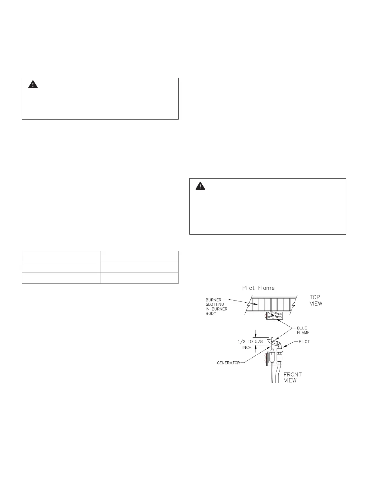
CHECK PILOT BURNER
The pilot ame should surround the generator tip 3/8-inch to 1/2-inch.
Pilot gas may need adjustment depending on the inlet pressure.
Increase or decrease the pilot ame to obtain proper setting.
BURNER FLAME CHARACTERISTICS
Start the furnace and let it operate at least 10 minutes. Open the
access door to view the burner ame. Limit your movements near the
furnace a few more minutes before making your nal observation.
The ame may look yellow due to dust particles in the room air.
The ame should change to a nice blue color with rm inner and
secondary cones. An occasional ash of orange might be seen as
dust particles burn in the ame. This is normal. No burner adjustment
is provided, or is necessary. Figure 16
TYPE OF GAS MANIFOLD PRESSURE, IN. W.C.
NATURAL 4.0
PROPANE 10.0
FIGURE 15
Start-Up Procedure