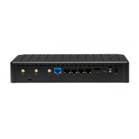
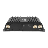
STEP 9: Power up the router.
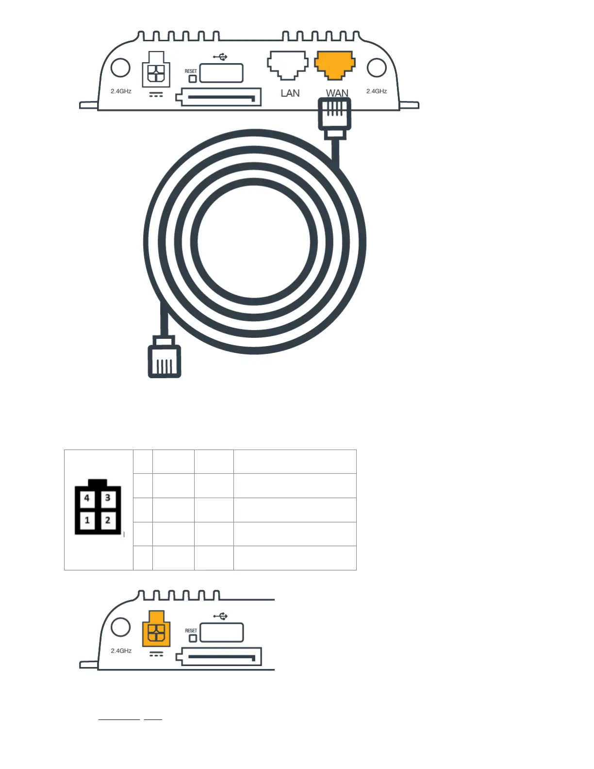
The AC power source includes a 4-pin slot plugin to connect directly to the router. The purpose of this configuration is to allow for using a 4-wire/GPIO cable
to hardwire power for DC connections or use GPIO. Refer to the following for pin configuration:
PIN Wire Color Definition Details
1 Black Ground Ground
2 Red Power 9-33 VDC
3 Orange Input 3V Input High Threshold (36V tolerant)
4 Blue Output General purpose I/O (GPIO)
1. Insert the 4-pin end of the power source into the four-pin port on the router, ensuring appropriate alignment of pins as illustrated above.
2. Plug the adapter into an electrical socket.
3. Allow 1 minute for the router to run through its bootup sequence.
Refer to the Understanding LEDs section of the guide for more information about LED indicator status.
 Loading...