Do you have a question about the Craftsman 113.29570 and is the answer not in the manual?
Securing the saw to prevent tipping and ensure stable operation.
Proper positioning of the saw for operator safety and visibility.
Understanding and preventing dangerous kickback incidents.
Essential personal protective equipment and body safety measures.
Importance of sharp, well-maintained cutting tools for safe operation.
Technical data for the saw's motor, including voltage, amperage, and RPM.
Information on thermal overload protection and safe motor operation.
Guidelines for safely connecting the saw to an electrical power source.
List of tools required for assembly and setup of the table saw.
Inventory of all individual components included with the saw.
Attaching the controls for blade height and angle adjustment.
Verifying the table insert is flush with the saw table surface.
Ensuring the blade is perpendicular to the saw table for accurate cuts.
Confirming the maximum blade height is within safe limits.
How to install optional table extensions for increased workspace.
Attaching the guide bars for the rip fence assembly.
Instructions for assembling the steel legs for the saw stand.
Procedures for securely mounting the saw onto its base or stand.
Adjusting table extensions to ensure they are flush and parallel.
Properly aligning the rip fence for accurate ripping operations.
Setting the rip scale pointer to zero for accurate measurements.
Correctly installing the safety blade guard and spreader assembly.
Operation and safety features of the power switch, including key lock.
Location and function of the motor's manual reset button.
How to use the handwheel to adjust blade height.
How to use the handwheel to adjust blade tilt angle.
Adjusting and using the rip fence for precise cuts.
Using the miter gauge for crosscutting and angled cuts.
Importance and installation of the safety blade guard.
Removing and installing the table insert for different operations.
Step-by-step guide for safely changing the saw blade.
Guidance on creating and using auxiliary tools like push sticks.
Instructions for making and using push sticks and blocks for safety.
How to create and use an auxiliary fence for specific cuts.
Methods for making straight cuts across the grain.
Techniques for making multiple identical cuts efficiently.
Performing angled cuts using the miter gauge.
Cutting across the grain at an angle to the blade's tilt.
Combining miter and bevel cuts for complex angles.
Cutting wood lengthwise with the grain.
Ripping wood at an angle to the blade's tilt.
Cutting wood lengthwise through its thickness.
Techniques for cutting large sheet materials.
Cutting a notch or step along the edge of material.
Cutting grooves or channels across the grain.
Using molding heads to shape wood edges.
Calibrating the miter gauge for accurate angle cuts.
Aligning the blade parallel to the miter gauge groove to prevent binding.
Adjusting blade tilt and ensuring squareness to the table.
Setting the correct blade height for safe and effective cutting.
Adjusting the handwheel mechanisms for smooth operation.
Oiling key parts to ensure smooth operation and longevity.
General troubleshooting steps for saw operation issues.
Diagnosing and fixing motor-related problems.
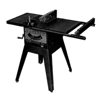
Detailed breakdown of parts shown in Figure 1.
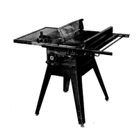
Detailed breakdown of parts shown in Figure 2.
Illustrated parts list for the rip fence assembly.
Illustrated parts list for the miter gauge assembly.
Illustrated parts list for the blade guard assembly.
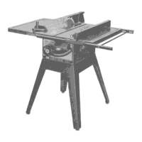
Illustrated parts list specific to Model 113.295750 (legs/extensions).
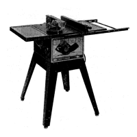
Illustrated parts list for table extensions.