7. Tighten the lock nut (6).
8. When the blade is exactly 90° (0°)
to the table, loosen the bevel
indicatorscrew (9) usinga Phillips
screwdriver.
9. Adjust the bevel indicator(10) to
the "0" mark on the bevel scale and
retighten the indicatorscrew (9).
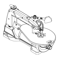
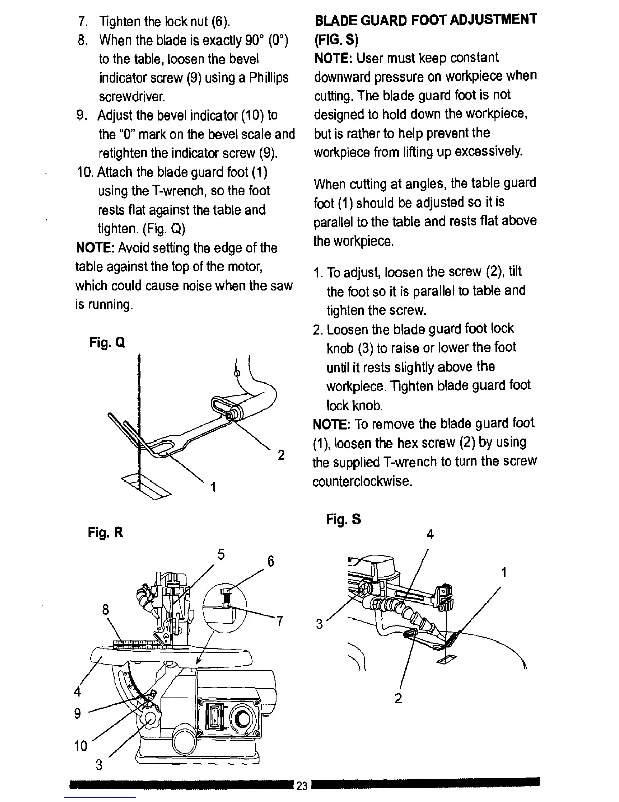
10.Attach the bladeguard foot (1)
usingtheT-wrench, so the foot
rests fiat againstthe table and
tighten.(Fig. Q)
NOTE: Avoid settingthe edge of the
table againstthe top of the motor,
whichcould cause noisewhen the saw
is running.
Fig. Q
2
1
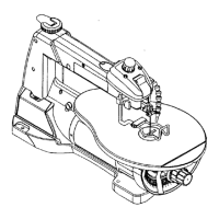
BLADE GUARD FOOT ADJUSTMENT
(FIG. S)
NOTE: User must keep constant
downwardpressure on workpiece when
cutting.The blade guard foot is not
designedto hold down the workpiece,
butis ratherto help prevent the
workpiece from liftingup excessively.
When cutting at angles, the table guard
foot (1) should be adjusted so it is
parallel to the table and rests flat above
the workpiece.
1.To adjust, loosen the screw (2), tilt
the foot so it is parallel to table and
tighten the screw.
2. Loosen the blade guard foot lock
knob (3) to raise or lower the foot
until it rests slightly above the
workpiece. Tighten blade guard foot
lock knob.
NOTE: To remove the blade guard foot
(1), loosen the hex screw (2) by using
the supplied T-wrench to turn the screw
counterclockwise.
4
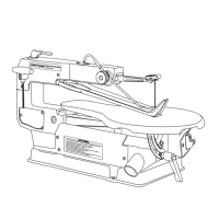
9
Fig. R
5 6
Fig. S
4
1
2
10
II III II 23 III I