NOTE:
o Thewashers(1/4"1/2-3/32)(5)are
notincludedwiththistablesaw.It
mustbepurchasedseparately.
o Rivingknifethicknessis0.09in.
o Themaximumradialdistance
betweentherivingknifeandthe
toothedrimofthesawbladeis0.12
in- 0.31in.(3mm- 8 mm)
o Thetipoftherivingknifeshallnot
belowerthan0.04in._ 0.2in.(1
mm_ 5mm)fromthetoothpeak.
o Therivingknifeisthinnerthanthe
widthofthekerfbyapproximately
1/64inoneachside.
8. Checktherivingknifeandblade
alignmentagainatboth0° and45°.
9. Addorremovethewashersuntilthe
alignmentiscorrect.
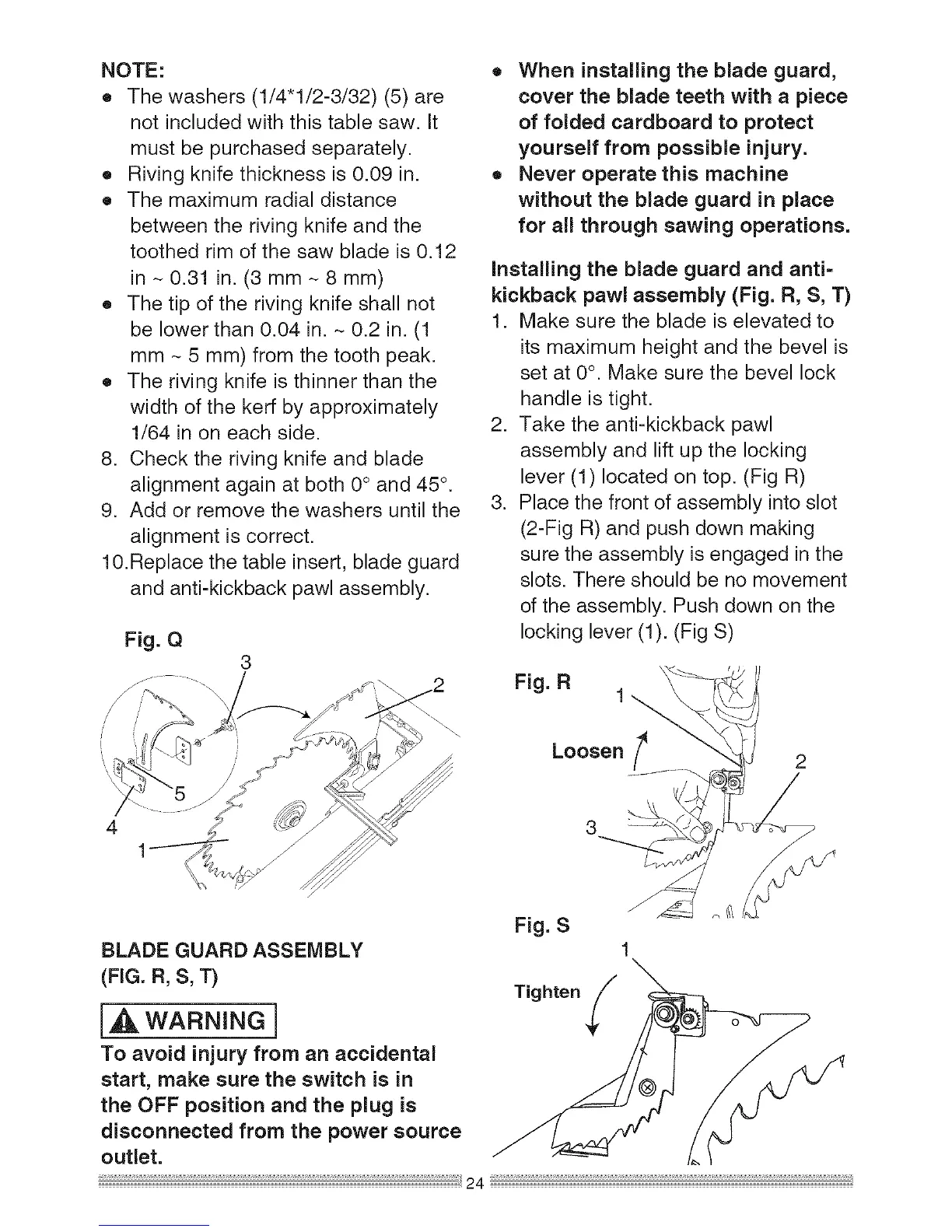
10.Replacethetableinsert,bladeguard
andanti-kickbackpawlassembly.
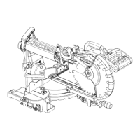
Fig.Q
3
4
1
BLADEGUARDASSEMBLY
(FIG.B,S,T)
i_ WARNING]
To avoid injury from an accidental
start, make sure the switch is in
the OFF position and the plug is
disconnected from the power source
outlet.
o When installing the blade guard,
cover the blade teeth with a piece
of folded cardboard to protect
yourself from possible injury.
o Never operate this machine
without the blade guard in place
for all through sawing operations.
installing the blade guard and anti=
kickback pawl assembly (Fig. R, S, T)
1. Make sure the blade is elevated to
its maximum height and the bevel is
set at 0°. Make sure the bevel lock
handle is tight.
2. Take the anti-kickback pawl
assembly and lift up the locking
lever (1) located on top. (Fig R)
3. Place the front of assembly into slot
(2-Fig R) and push down making
sure the assembly is engaged in the
slots. There should be no movement
of the assembly. Push down on the
locking lever (1). (Fig S)
Tighten
 Loading...