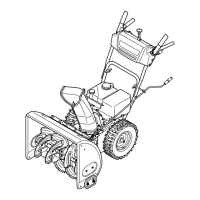
4. Squeeze the trigger on the joystick and rotate the chute
by hand to face forward. The holes in the chute rotation
assembly will be facing up. See Fig. 3-6.
NOTE: The chute will not rotate without squeezing the
trigger on the joystick.
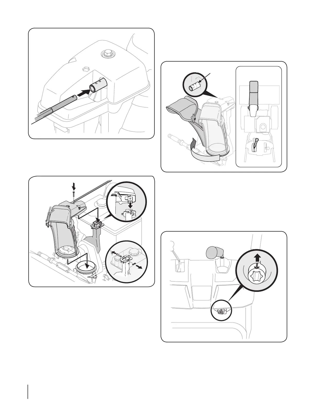
5. Rotate the joystick to 1 o’clock position so the silver arrow
on the pinion gear faces upward See Fig. 3-7).
NOTE: The joystick will be angled slightly to the right at the
one o’clock position. See “Top View” in Fig. 3-6.
NOTE: The pinion gear is located on the front of the unit
below the control panel.
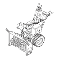
3. Place chute onto chute base with the chute control rod
positioned under the handle panel. Reinstall the hex bolt
previously removed but do not secure with wing nut at this
time. See Fig. 3-5.
Fig. 3-7
Fig. 3-5
Fig. 3-4
Fig. 3-6
Top View
Chute Rotation
Assembly
8 Section 3— ASSembly & Set-Up