ENGLISH
8
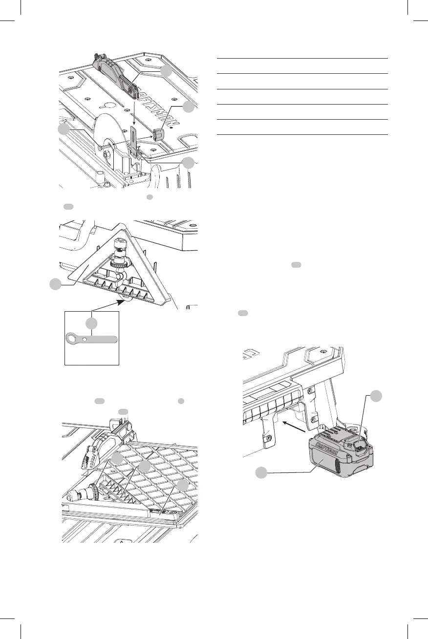
Fig.G
18
17
14
5
8. After blade installation, the wrench
4
and edge
guide
10
can be stored on the back of the tool.
Fig.H
10
4
To Attach the Edge Guide (Fig. I)
The edge guide can be installed 1 of 2 ways, 45° or 90°.
1. Place edge gude
10
on the cutting cart fence
7
.
2. Turn the edge guide lock
11
clockwise totighten.
Fig. I
7
10
11
Specifcations
Voltage 20V
RPM 2800
Depth of Cut 1.25" (32 mm)
Blade Size 7" (178 mm)
Arbor Size 5/8" (16 mm)
OPERATION
WARNING: To reduce the risk of serious personal
injury, turn unit off and remove the battery pack
before making any adjustments or removing/
installing attachments or accessories. An
accidental start-up can causeinjury. Make sure the
switch is in the OFF position.
Installing and Removing the Battery Pack
(Fig. J)
NOTE: For best results, make sure your battery pack is
fullycharged.
To install the battery pack
19
into the tool, align the battery
pack with the rails inside the tool and slide it into position
until the battery pack is firmly seated in the case and ensure
that it does notdisengage.
To remove the battery pack from the tool, press the release
button
20
and firmly pull the battery pack out of the tool.
Insert it into the charger as described in the charger section
of thismanual.
Fig. J
20
19
Tool Placement (Fig. K)
Place saw on a stable, levelsurface.