16
1.3.3 Fuse and Circuit Breaker Selection
Reference Table 1.3.2 to properly apply fuses and circuit breakers to the drive.
Table 1.3.2: Fuse and Circuit Breaker Selection
SV100 Drive
Voltage
Ref.
HP
SV100
Part Number
Fuse Rating
Class (J)
Molded Case
Circuit Breaker
1 446485-01 10 A 15 A
2 446485-02 10 A 15 A
3 446485-03 20 A 25 A
230V
5 446485-04 25 A 30 A
1 446485-05 5 A 5 A
2 446485-06 8 A 10 A
3 446485-07 10 A 15 A
460V
5 446485-08 15 A 20 A
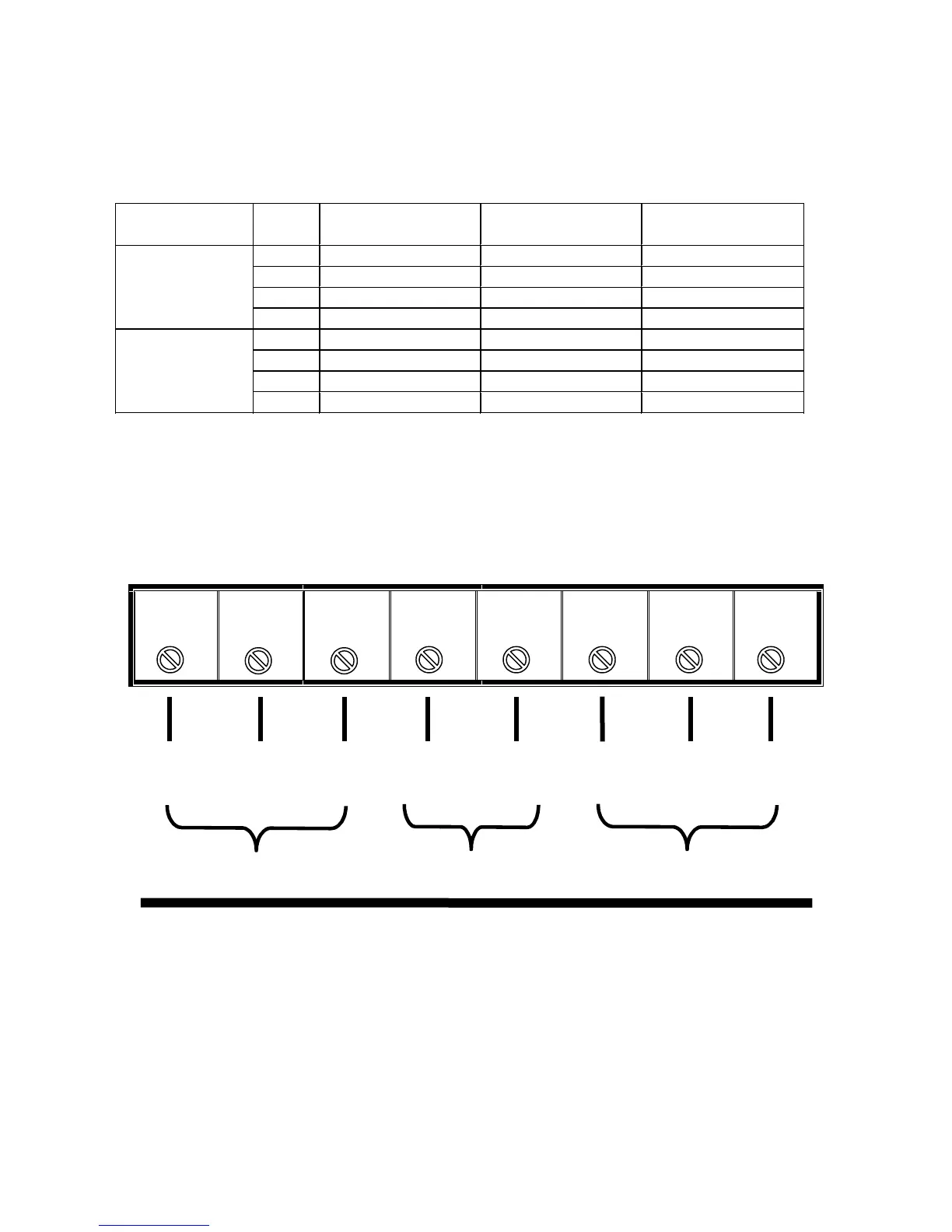
1.3.4 Power Lead Wiring
Use Figure 1.3.2 as shown below to assist in wiring the power leads to the drive.
Fig. 1.3.2: Input / Output Power and Dynamic Braking Resistor Wiring Diagram.
Arrangement of Power Terminal Strip
RSTB1B2UVW
L1 L2 L3 B1 B2 T1 T2 T3
3 Phase Input Power Dynamic Braking 3 Phase Output to Motor
230 VAC or 460 VAC Resistor Unit
Note 1:
Slotted Tongue Terminals are recommended for connections shown in
Figure 1.3.2.
Note 2:
Use drive chassis to ground the drive to the panel.