22
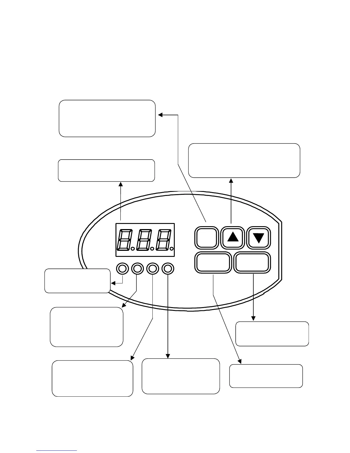
Section 2.1: Keypad Layout
The SV100 keypad consists of an LED display, status lights, and keys for easy
programming. Fig. 2.1.1 below illustrates the layout of the SV100 keypad.
Figure 2.1.1 – SV100 keypad layout
Run LED
•
ON during motor
operation
UP
/
DOWN Arrow Keys
•
Used to scroll up or down through function
parameters
• Increase or decrease the data in
programming mode
Display
• Displays frequency, current, group
functions and function data
FUNC Key
• (Press Once) Starts Programming
mode
•
(Press 2
nd
Time) Completes
Programming mode
FWD LED
•
Blinks during Up / Forward
while in Accel / Decel
• ON during Up / Forward at
selected speed
RUN Key
• Does not have any control
of drive operation
REV LED
•
Blinks during Down / Reverse
while in Accel / Decel
• ON during Down / Reverse at
selected speed
SET LED
• ON when in Program mode
• OFF when not in Program
mode
STOP/RST
•
Reset button for fault
condition
FUNC
RUN
STOP/RST