72
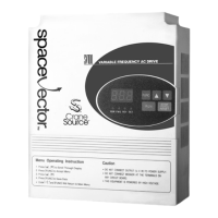
Fig. 5.3.1: Analog Control Source Diagrams
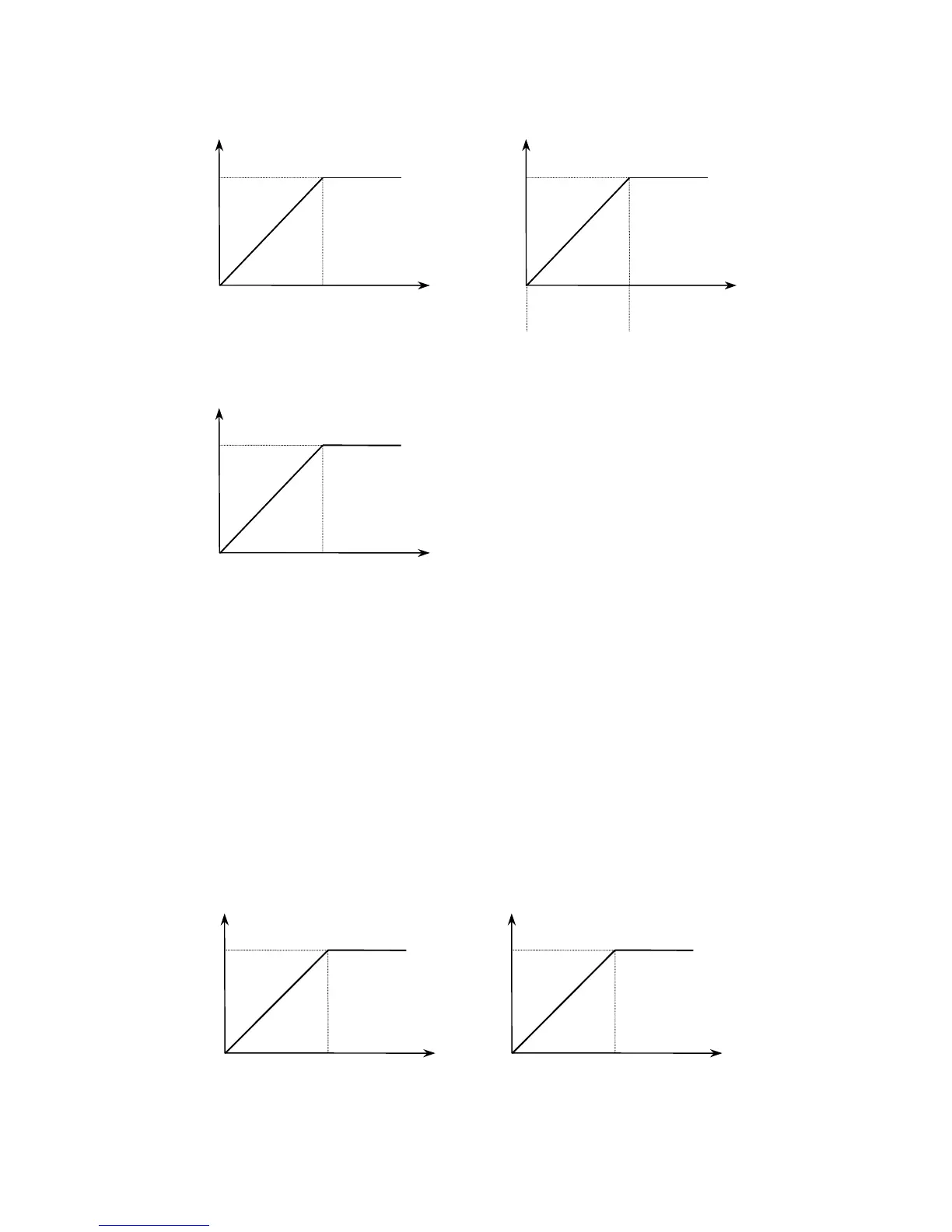
H8, Analog Input Gain, establishes the correct ratio between the analog input signal
and its maximum speed reference of the drive. For example, if the drive needs to
accept +5 VDC analog signal as its maximum speed reference instead of +10 VDC,
by setting H8 to 50% the drive will calculate its maximum analog input as
10 VDC x (0.5) = 5 VDC. This establishes a +5 VDC input signal as the maximum
speed reference. See Fig. 5.3.2.
Fig. 5.3.2: Analog Input Gain
Frequency
Freq. ref.
F_max
0V
10V
[H6 = Voltage]
Frequency
Freq. ref.
F_max
[H6 = Volt + Curr.]
Frequency
Freq. ref.
F_max
[H6 = Current]
4mA 20mA
4 ~ 20mA
+ 0 ~ 10V
Frequency
Freq. ref.
F_max
0V
4mA
10V(20mA)
[H8 = 100%]
Frequency
Freq. ref.
F_max
[H8 = 50%]
0V
4mA
5V(12mA)
H6 = 1: Current
H6 = 0: Voltage H6 = 2: Voltage + Current