73
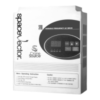
H8 is used to set the ratio between the maximum analog input signal and the
maximum frequency reference. H9, Analog Input Bias, establishes the ratio between
the minimum analog input signal and the minimum frequency reference. For
example, if H9 is set at 50% and the analog input signal is 0 VDC, then the drive will
calculate its minimum speed reference (maximum speed x H9) which becomes half
of the set maximum frequency.
Fig. 5.3.3: Analog Input Bias
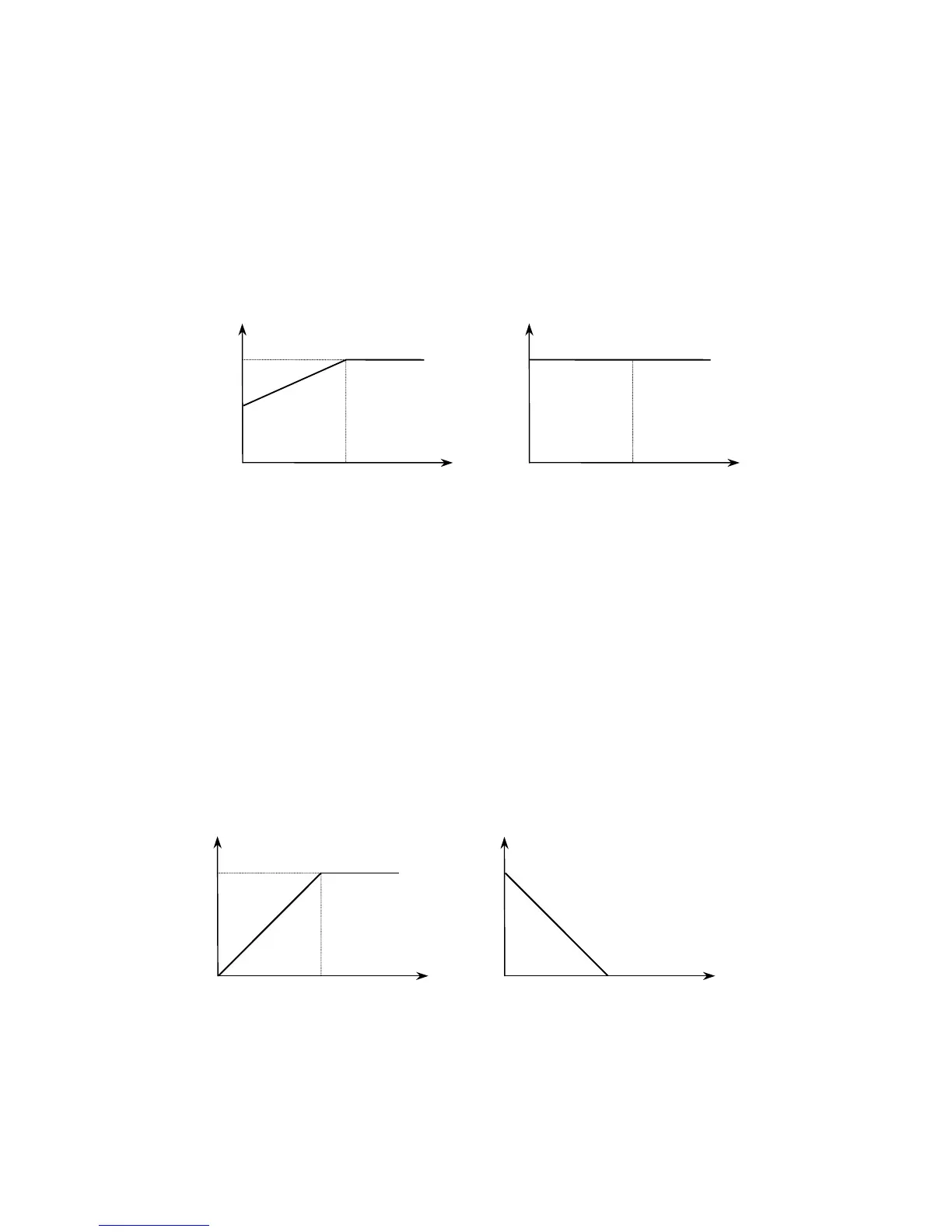
H10, Analog Input Direction, establishes the analog input versus frequency refer-
ence slope that is either a positive or negative slope. When set to 0: Direct the
analog command signal (0 ~ 10VDC or 4 ~ 20mA) represents an increasing or
positive slope. When set to 1: Inverse then the signal (0 ~ 10VDC or 4 ~ 20mA)
represents a decreasing or negative slope. See Fig. 5.3.4.
Fig. 5.3.4: Analog Reference Slope
Frequency
Freq. ref.
Fmax
0V
4mA
10V(20mA)
[H9 = 50%]
Frequency
Freq. ref.
Fmax
[H9 = 100%]
0V
4mA
10V(20mA)
Fmax/2
Frequency
Freq. ref.
Fmax
0V
4mA
10V(20mA)
[H10 = Direct]
Frequency
Freq. ref.
Fmax
[H10 = Invert]
0V
4mA
10V(20mA)
[H10 = In-
verse]