Product Manual — Doc.
9323C
IV-CAMA3-20-N-W-1B, IV-CAMA3-20-N-SLVR-1B, IV-CAMA3-20-W-1B, and IV-CAMA3-20-SLVR-
1B • 22
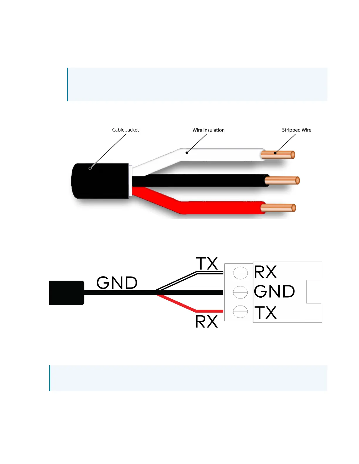
3. Use wire strippers to remove the other end of the RS-232 DB9 cable. Then, strip the RS-232 cable
insulation to expose the three wires inside. The colored cables correspond to the following
connections:
l
TX: White sleeved wire
NOTE: In some circumstances, the RS-232 DB9 cable will have a blue sleeved wire
instead of the white sleeved wire. For the purposes of this procedure, the blue sleeved
wire is identical to the white sleeved wire.
l
RX: Red sleeved wire
l
Ground: Black sleeved wire
4. Connect the TX (white sleeve) wire to the RX terminal on the Inogeni terminal block.
5. Connect the Ground (black sleeve) wire to the GND terminal on the Inogeni terminal block.
6. Connect the RX (red sleeve) wire to the TX terminal on the Inogeni terminal block.
7. Insert the Inogeni terminal block into the VISCAport on the Inogeni 4KXUSB3 converter.
8. Connect the 3G-SDI cable from the camera into the SDI IN port on the Blackmagic Design SDIto
HDMI3Gconverter.
NOTE:Do not use the HDMI cable to cover long wiring distances. The 3G-SDI cable provides
the best video output over long wiring distances.
 Loading...