11 • CEN-GW1 and CENI-GW1 Product Manual — Doc. 9195A
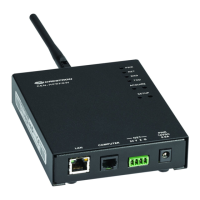
SETUP (1) Recessed pushbutton with red LED
Used to set up connection with the control system via Ethernet;
To factory reset the gateway, press and hold SETUP until the SETUP LED
flashes 6times.
RESET (1) Recessed pushbutton;
To reboot the gateway, press and hold RESET for 8 seconds.
LAN PoE (1) Green and (1) Amber LED;
Green indicates Ethernet link status;
Amber indicates Ethernet activity
Connectors
ANTENNA EX/ER (1) Connection for supplied EX/ER antenna or antenna extender
ANTENNA SG (1) Connection for supplied SG antenna or antenna extender;
CEN-GW1: Yellow bands around the top;
CENI-GW1: Gray bands around the top
COMPUTER (1) Micro-B USB female;
Computer console port, installer use only;
For setup and firmware upgrades
G (1) 4-40 screw, chassis ground lug
24VDC 0.75A (1) 2.1 x 5.5 mm DC power connector;
24VDC power input;
PW-2407WU power pack sold separately
LAN PoE (1) 8-pin RJ-45, female;
10BASE-T/100BASE-TX Ethernet port;
Power over Ethernet compliant
Power
Power over Ethernet IEEE 802.3at Type 1 (802.3af compatible) Class 3 (5.3 W) PoE Powered Device
Power Pack 0.75A (minimum) @ 24VDC (PW-2407WU sold separately)
Power Consumption 5.3 W typical
Environmental
Temperature 41° to 104 °F (5° to 40 °C)
Humidity 10% to 90% RH (noncondensing)
Heat Dissipation 18.1 BTU/hr
Construction
Enclosure IFE small form factor, black and blue plastic with die-cast zinc top cover
Mounting Freestanding, stackable, surface mount, or 35mmDIN EN 60715 rail mount;
Occupies 8 DIN module spaces (144 mm);
Surface/DIN rail mounting bracket included;
Rack mount and pole mount kits sold separately

 Loading...