14 • Cresnet® Network Design Guide — Doc. 9292A
Wiring and Connectors
The following sections provide information about Cresnet wiring and connectors within a
Cresnet network system.
NOTE:To view and download drawing packages that show common Cresnet wiring
scenarios, refer to Crestron Online Help article 1001565.
Overview
Observe the following about Cresnet wiring and connectors:
l
All wire is calculated in American Wire Gauge (AWG)sizes
l
All network wire must consist of two twisted pairs and a drain wire:
o
One twisted pair of 24VDCpower and ground (GND) conductors
o
One twisted pair of Y and Zdata conductors wrapped in a foil shield
o
One stranded jacketless conductor (for drain wire)
l
Standard Cresnet wire uses the following specifications:
o
18AWG(0.82mm
2
) red/black twisted pair is used for 24VDC power and ground.
o
22AWG(0.33mm
2
) blue/white twisted pair is used for data (Yand Z) with
aluminum/polyester foil shield (providing 100%coverage)
o
24AWG(0.20mm
2
) stranded tinned copper drain wire
l
High-Powered (HP)Cresnet wire uses the following specifications:
o
12AWG(3.31mm
2
) red/black twisted pair is used for 24VDC power and ground.
o
22AWG(0.33mm
2
) blue/white twisted pair is used for data (Yand Z) with
aluminum/polyester foil shield (providing 100%coverage)
o
24AWG(0.20mm
2
) stranded tinned copper drain wire
l
Cresnet cables are rated for low-voltage (60VAC/VDC or less) applications.
CAUTION:Cresnet cables should never be used within high-voltage (60VAC/VDC or
more) applications.
l
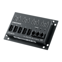
The following connectors are used by Cresnet-supported devices. Each connector type
supports wire termination for Cresnet power, data, and ground.
o
Black 4-pin terminal blocks with 5mm spacing
o
Green 4-pin terminal blocks with 3.5mm spacing
o
RJ-11 style Cresnet distribution ports (legacy installations only)