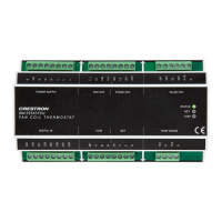
The Crestron DIN-1TSTAT8 is an 8-zone radiant heat thermostat designed for DIN rail mounting. It is specifically engineered for heat-only applications, making it suitable for systems utilizing radiators or radiant floor heating. The device requires a Crestron control system to function, allowing for customized control and scheduling of heating zones.
Function Description:
The DIN-1TSTAT8 manages the heating valve for each of its eight zones through SPDT relay control outputs. An additional ninth SPDT relay output is provided for a main valve control. Each relay is rated for 1/2 HP at 240VAC, 50/60 Hz, and includes both normally open (NO) and normally closed (NC) contacts.
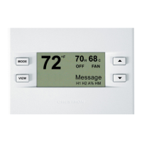
Remote temperature sensors are used to eliminate the need for individual wall-mounted thermostats in each zone. Heating setpoints for each zone are configured by the user via the Crestron control system and are then stored in the DIN-1TSTAT8's memory.
In the event of a lost user setpoint or a disruption in communication with the control system, the DIN-1TSTAT8 enters a failsafe operating mode. During this mode, the thermostat maintains a preset temperature to ensure the space remains heated until the user setpoint is restored or communication is re-established. The failsafe setpoint is factory defaulted to 20°C (68°F) but is user-adjustable from 5°C (41°F) to 20°C (68°F) within the control system program.
A main valve delay feature allows for a configurable delay from 0 to 5 minutes when a heat call is initiated, with a factory default of 5 minutes. This delay can be adjusted to align with the specifications of the valve manufacturer.
Important Technical Specifications:
- Contact Rating: 1/2 HP @ 240VAC, 50/60 Hz per zone/channel. Provides eight SPDT heat zone valve control outputs and one SPDT main valve control output.
- Temperature Sensing:
- Measurement Range: 0° to 43°C (32° to 110°F).
- Temperature Tolerance: ±0.5°C (±1°F) over full range; +0.1°/-0.4°C (±1°F) at room temperature.
- Setpoint Range (Heat Only): 3° to 32°C (38° to 90°F).
- Temperature Offset: ±3°C (±6°F); in steps of 0.1° per temperature sensor input.
- Failsafe Setpoint: 20°C (68°F) factory default, user-adjustable from 5° to 20°C (41° to 68°F).
- Main Valve Delay: 5 minutes factory setting, adjustable from 0 to 5 minutes.
- Communications: Cresnet secondary mode.
- Connections:
- 1-8 (Zone Valve Outputs): Eight sets of 3 captive screw terminals (C, NC, NO) for zone valve control. Each output provides one SPDT relay.
- MAIN (Main Valve Output): Three captive screw terminals (C, NC, NO) for main valve control. Provides one SPDT relay.
- NET (Cresnet): Two 4-pin detachable terminal blocks for Cresnet secondary port with hardwire parallel pass-through.
- TEMP SENSE 1-8: Eight 2-pin detachable terminal blocks for temperature sensor inputs. Each input accepts one sensor (e.g., CHVI-RTS-1G-SM-W, CHVI-RTS-1G-N-W, CHV-RTS, or CHV-RSS). Requires dedicated low-capacitance twisted pair wire (<7 nF per run). Supports wire lengths of 76 m (250 ft) using CAT3 or 152 m (500 ft) using CAT5. Thermostat wire (18-20 gauge) may be used up to 30 m (100 ft) but is not recommended.
- Controls and Indicators:
- 1-8: Eight red LEDs and eight pushbuttons. Buttons toggle zone output on/off (press and hold 10 seconds for test call). LEDs indicate zone output status (flashes with heat call, steady without heat call).
- MAIN: One red LED and one pushbutton. Button toggles main output on/off when held 10 seconds. LED indicates main output status (flashes with heat call, steady without heat call).
- SETUP: One recessed pushbutton and one red LED for Cresnet TSID (touch-settable ID).
- PWR: One green LED, indicates device is powered via Cresnet.
- NET: One yellow LED, indicates Cresnet communication with the control system.
- RESET: One recessed pushbutton for hardware reset.
- Power:
- Cresnet Power Usage: 6 W (250 mA @ 24VDC).
- Power Consumption: <6 W.
- Environmental:
- Temperature: -18° to 43°C (0° to 110°F).
- Humidity: 10% to 90% RH (noncondensing).
- Heat Dissipation: 20 BTU/hr maximum.
- For indoor use only.
- Construction:
- Housing: Light gray polycarbonate housing with polycarbonate label overlay, UL94 V-0 rated.
- Mounting: 35 mm DIN EN 60715 rail mount, DIN 43880 form factor for enclosures with 45 mm front panel cutout, occupies 9 DIN module spaces (162 mm).
- Dimensions:
- Height: 94 mm (3.68 in.).
- Width: 161 mm (6.33 in.).
- Depth: 60 mm (2.34 in.).
- Weight: 0.5 kg (1.08 lb).
- Compliance: CE, IC, FCC Part 15 Class B digital device.
Usage Features:
- Customized Control and Scheduling: Integration with a Crestron control system allows for flexible temperature adjustments and scheduling from various interfaces such as touch screens, handheld remotes, mobile apps, or computers.
- Test Mode: After installation and programming, a Test mode can be activated to verify the correct operation of each heating zone. Pressing and holding a zone's 1-8 button for 10 seconds initiates a 5-minute heat call for that zone. The zone LED flashes during this period, and the zone valve, main valve, and DIN-1TSTAT8 return to their previous states upon completion.
- Manual Zone Control: Individual 1-8 buttons allow for manual toggling of each heat zone on and off.
- Manual Main Valve Control: The MAIN button, when held for 10 seconds, allows for manual toggling of the main valve on and off.
- Temperature Sensor Monitoring: Temperature sensors read room temperature once per second. If a sensor is not connected or fails to send a valid value for 10 minutes, the corresponding zone valve turns off and remains off.
- Cresnet Connectivity: The device connects to a Crestron control system and other Cresnet devices via its NET terminals, facilitating system integration.
Maintenance Features:
- Troubleshooting Guide: The manual provides a basic troubleshooting table for common issues such as the thermostat not receiving a signal, suggesting checks for improper connections or incomplete circuits in wiring.
- Hardware Reset: A recessed RESET pushbutton is available for performing a hardware reset.
- DIN Rail Mounting and Removal: The device is designed for easy mounting and removal from a 35 mm DIN rail, facilitating installation and servicing. Removal involves turning off power, disconnecting wiring, pulling down a DIN rail release tab with a flat-head screwdriver, and tilting the device away from the rail.
- Ventilation Requirements: It is important to install the DIN-1TSTAT8 in a well-ventilated area and avoid blocking venting holes to ensure proper operation and longevity.
- Software and Documentation Resources: Crestron provides various online resources, including Crestron True Blue Support, a Resource Library, Online Help (OLH), and a Training Institute (CTI) Portal for support and training. Programmer and developer resources are also available for help files and documentation related to programming tools and APIs. Product certificates can be accessed online.