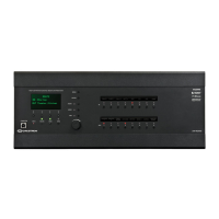
DigitalMedia™ Switchers Crestron DM-MD8X8/16X16/32X32
Ear Attachment for Rack Mounting (DM-MD8X8 shown)
USE COVER SCREWS
4. Repeat procedure (steps 1 through 3) to attach the remaining ear to the
opposite side.
Stacking
Four “feet” are provided with the DM-MD8X8, DM-MD16X16 and the
DM-MD32X32 so that if the units are not rack mounted, the rubber feet can provide
stability when the units are placed on a flat surface or stacked. These feet should be
attached near the corners prior to the hookup procedure.
NOTE: No more than two DM switchers should be stacked.
Hardware Hookup
Connect the Device
Make the necessary connections as called out in the illustration that follows this
paragraph. For details on making connections to installed DM input cards and DM
output cards, refer to “Appendix A: Hardware Hookup for DM Cards” on page 75.
Apply power after all connections have been made.
When making connections to the DM switcher, use Crestron power supplies for
Crestron equipment.
34 x
DigitalMedia™ Switchers: DM-MD8X8/16X16/32X32 Operations Guide – DOC. 6755C
 Loading...