DO GUIDE
DO Connect the Device
Connect the device as required for the application.
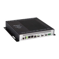
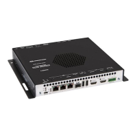
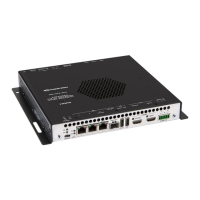
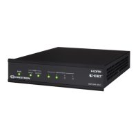
Front Panel Connections
Rear Panel Connections
NOTE: The DM-NVX-350 and DM-NVX-351 can be congured to use either the DEVICE port or the
HOST port. Both ports cannot be used simultaneously.
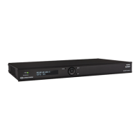
DM-NVX-350/DM-NVX-351
DM NVX™ 4K60 4:4:4 HDR Network AV Encoders/Decoders
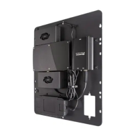
DO Install the Device
The Crestron
®
DM-NVX-350 and DM-NVX-351 can be mounted onto a at surface or rack rail.
Mount onto a Flat Surface
Using four mounting screws (not included), mount the device onto a at surface such as a wall or the
underside of a table.
NOTE: Fan ventilation holes are provided on ve sides of the device. If the installation necessitates
that another object be positioned ush against the ventilation holes on one side of the device, leave a
minimum clearance of 2 inches of space on all other sides containing ventilation holes.
Mount onto a Rack Rail
Using two mounting screws (not included), mount the left or right mounting ange of the device onto
the front or rear rail of a rack.
DO Check the Box
QTY ITEM PART NUM.
1 Cable, USB 2.0, A - B, 6’ (1.83 m) 2014966
1 Connector, 4-Pin 2003576
2 Connector, 5-Pin 2003577
1 Power Cord, 5' 10" (1.78 m) 2042043
1 Power Pack, 24 Vdc, 2.5 A, 100-240 Vac 2045873
SERIAL:
To serial port
on PC
(cable included)
USB:
To USB
port
on PC
24V:
24 Vdc from
included power pack
COM:
To
RS-232
device
Ground
IR 1–2:
To IR
controllable
devices
DEVICE:
To
USB host
HOST:
To
USB
device
HDMI
®
OUTPUT:
To
HDMI
display
HDMI INPUTS
1–2:
From
audio/video
sources
AUDIO I/O:
Balanced/
unbalanced
stereo line
level audio
input or output
To SFP
port of
Ethernet
switch or
other
DM-NVX
device
10BASE-T/
100BASE-TX/
1000BASE-T to
Ethernet switch,
local network
device, or
other DM NVX™
1–2:
3: