DigitalMedia 8G+™ Transmitter 201 Crestron DM-TX-201-C
Connectors, Controls & Indicators (Continued)
# CONNECTORS,
CONTROLS &
INDICATORS
DESCRIPTION
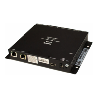
10 DM OUT
4, 5
AMBER
LED
GREEN
LED
PIN 8
PIN 1
(1) 8-pin RJ-45 female, shielded, with two
LED indicators;
DM 8G+ output, accepts power over DM
6
;
Connects to DM 8G+ input of a DM switcher,
receiver/room controller, or other DM device
via CAT5e or Crestron DM-CBL-8G cable
7
;
Green LED indicates DM link status;
Solid amber LED indicates HDCP video;
Blinking amber LED indicates non-HDCP
video
11
HDMI OUT
(1) 19-pin Type A HDMI female;
HDMI digital video/audio output;
Supports DVI
1
12
PWR
24 VDC
0.75A
(1) 2.1 mm barrel DC power jack;
24 Volt DC power input;
Power pack included
13 Power LED
(1) Green LED, indicates operating power
supplied from local power pack or from DM
14
(1) 6-32 screw, chassis ground lug
1. HDMI requires an appropriate adapter or interface cable to accommodate a DVI or DisplayPort
Multimode signal. CBL-HD-DVI interface cable sold separately.
2. The RGB input can accept component, composite, and S-video signals via direct interface to Crestron
MPS Series products (sold separately) or through an appropriate adapter (not included). Input sync
detection is not provided for composite or S-video signal types through the RGB connection.
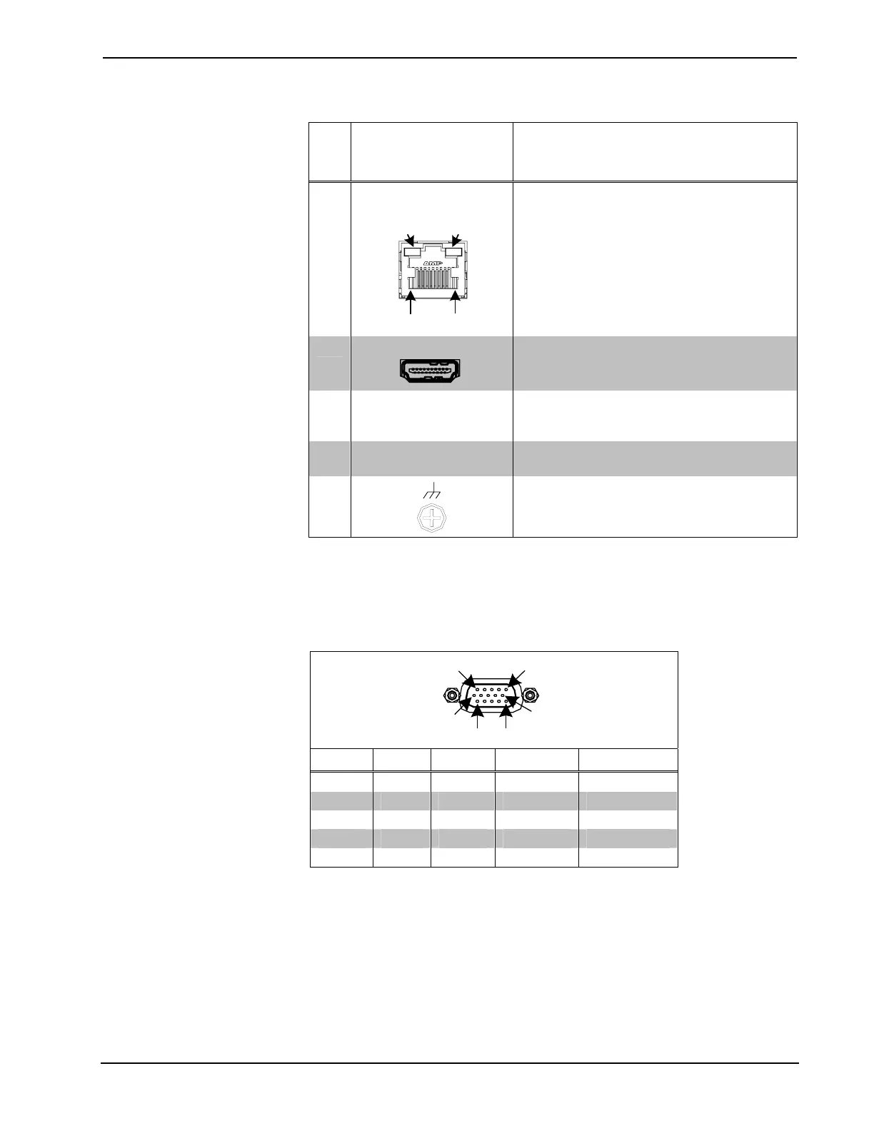
3. Refer to the following table for the RGB IN connector pinouts.
RGB IN Connector Pinouts
PIN 1 PIN 5
PIN 10
PIN 6
PIN 11
PIN 15
PIN # RGB YP
b
P
r
S-VIDEO COMPOSITE
1 R P
r
C
2 G Y Y
3 B P
b
Comp
13 H
14 V
4. To determine which is pin 1 on the cable, hold the cable so the end of the eight pin modular jack is
facing away from you, with the clip down and copper side up. Pin 1 is on the far left.
12 • DigitalMedia 8G+™ Transmitter 201: DM-TX-201-C Operations & Installation Guide – DOC. 6958B
 Loading...