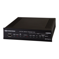
Crestron DM-TX-201-C DigitalMedia 8G+™ Transmitter 201
Connectors, Controls & Indicators
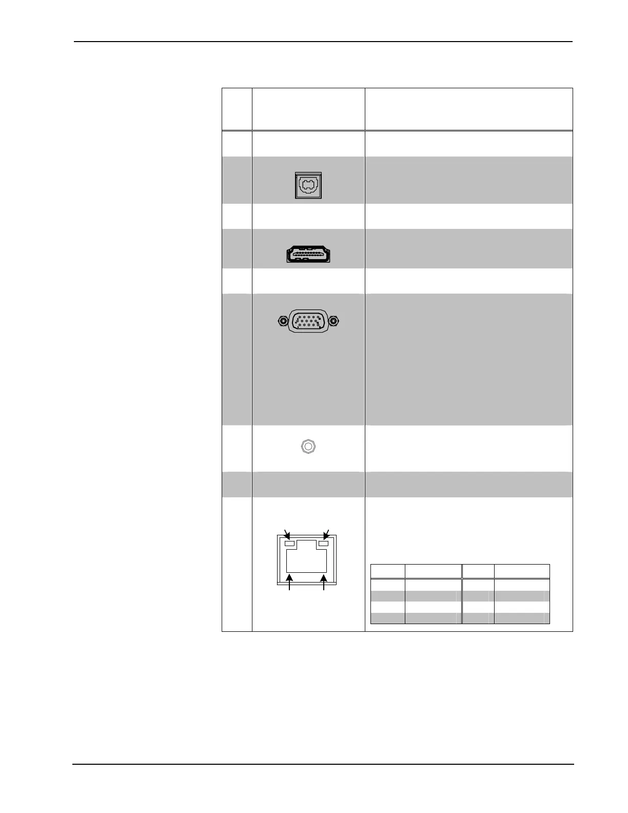
# CONNECTORS,
CONTROLS &
INDICATORS
DESCRIPTION
1 RESET
(1) Miniature recessed push button for
hardware reset
2
USB HID
(1) USB Type B female;
USB 1.1 device port for connection to the
USB host interface of a computer or other
USB HID-compliant host device
3 HDMI IN LED
(1) Green LED, indicates HDMI input is
selected
4
HDMI IN
(1) 19-pin Type A HDMI female;
HDMI digital video/audio input;
Supports DVI and DisplayPort Multimode
1
5 RGB IN LED
(1) Green LED, indicates RGB input is
selected
6
RGB IN
(1) DB15HD female;
RGB (VGA), component, S-video, or
composite video input
2, 3
Formats: RGBHV, RGBS, RG
S
B, YP
b
P
r
,
Y/C,
NTSC, PAL;
Input level: 0.5 to 1.5 V
p-p
with built-in DC
restoration;
Input impedance: 75 Ω;
Sync input type: Autodetect RGBHV, RGBS,
RG
S
B, YP
b
P
r
;
Sync input level: 3 to 5 V
p-p
;
Sync input impedance: 1 kΩ;
7
AUDIO IN
(1) 3.5 mm TRS mini phone jack;
Unbalanced stereo line level audio input;
Input impedance: 10 kΩ;
Input level: 2 V
rms
maximum
8
SETUP
(Button and LED)
(1) Miniature recessed push button for
Ethernet setup and (1) red LED
9
LAN
4
GREEN
LED
AMBER
LED
PIN 8
PIN 1
(1) 8-pin RJ-45 female, shielded, with two
LED indicators;
10BASE-T/100BASE-TX Ethernet port;
Green LED indicates Ethernet link status;
Amber LED indicates Ethernet activity
PIN SIGNAL PIN SIGNAL
1 TX + 5 N/C
2 TX - 6 RX -
3 RX + 7 N/C
4 N/C 8 N/C
(Continued on following page)
Operations & Installation Guide – DOC. 6958B DigitalMedia 8G+™ Transmitter 201: DM-TX-201-C • 11

 Loading...